Non-contact charging system, non-contact charging method, non-contact charging type vehicle, and non-contact charging management apparatus

a charging management and non-contact technology, applied in charging stations, electric devices, transportation and packaging, etc., can solve the problem of reducing the accuracy of the above-mentioned pairing

Active Publication Date: 2015-11-24
TOYOTA JIDOSHA KK
View PDF91 Cites 15 Cited by
  • Summary
  • Abstract
  • Description
  • Claims
  • Application Information

AI Technical Summary

Benefits of technology

[0008]Accordingly, it is an objective of the present invention to provide a non-contact charging system, a non-contact charging method, a non-contact charging type vehicle, and a non-contact charging management apparatus that allow easy and accurate identification of a charging target device, including a vehicle such as an automobile or a portable device, and perform non-contact charging on the charging target device.Means for Solving the Problems
[0063]In the above-described configuration, the management center controls the area IDs collectively and transmits each area ID to the corresponding charging target device directly or indirectly. Accordingly, even when the charging apparatus has a large number of charging areas or the charging areas are located at separate positions in a wide range, the non-contact charging management apparatus is capable of accurately identifying each charging target device to be recharged in the corresponding charging area and recharging the identified charging target device. That is, the non-contact charging management apparatus manages a large number of area IDs used for multiple charging areas located in a wide range collectively through the management center. As a result, the non-contact charging management apparatus becomes more versatile.

Problems solved by technology

This decreases accuracy in the aforementioned pairing.

Method used


Image

  • Non-contact charging system, non-contact charging method, non-contact charging type vehicle, and non-contact charging management apparatus
  • Non-contact charging system, non-contact charging method, non-contact charging type vehicle, and non-contact charging management apparatus
  • Non-contact charging system, non-contact charging method, non-contact charging type vehicle, and non-contact charging management apparatus

Examples


first embodiment

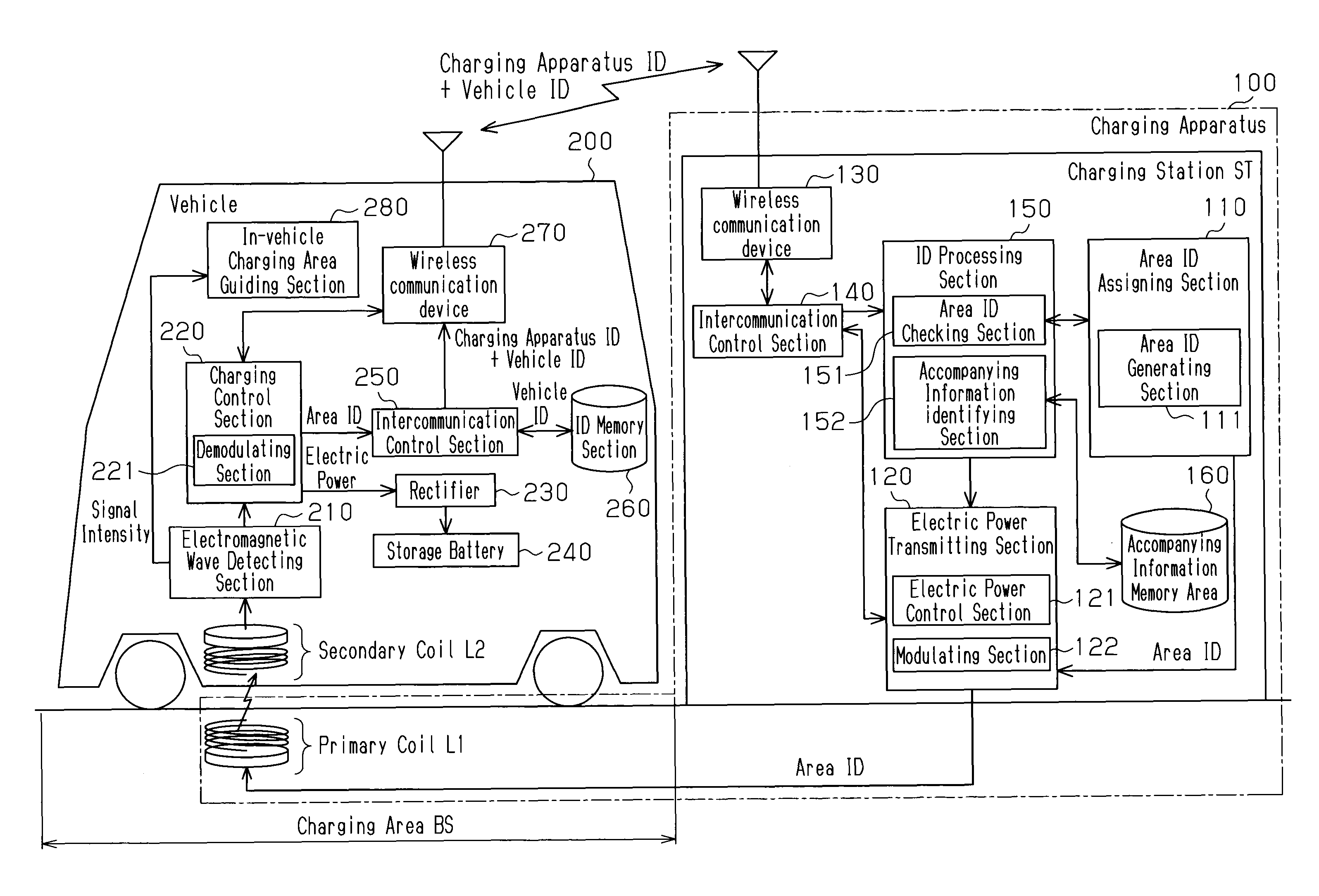
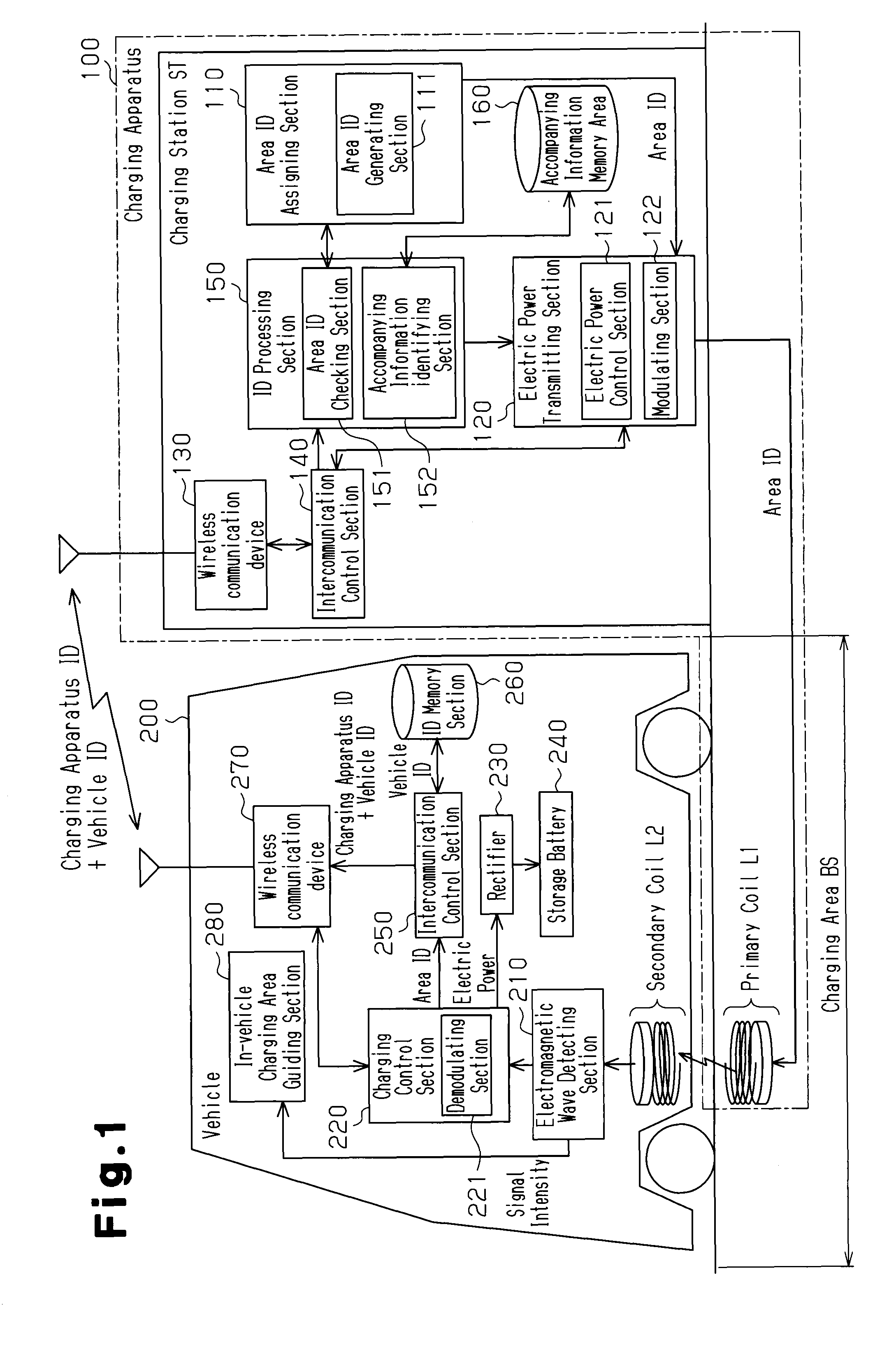
[0075]A first embodiment of a non-contact charging system, a non-contact charging method, a non-contact charging type vehicle, and a non-contact charging management apparatus according to the present invention will now be descried with reference to FIGS. 1 to 7. In the first embodiment, a charging target device is an electric vehicle or a hybrid vehicle having a storage battery serving as an electric power supply for an electric motor.

[0076]As illustrated in FIG. 1, the non-contact charging system of the first embodiment is configured mainly by a charging apparatus 100, which transmits electric power to a charging target device in a non-contact manner, and a vehicle 200 serving as the charging target device.

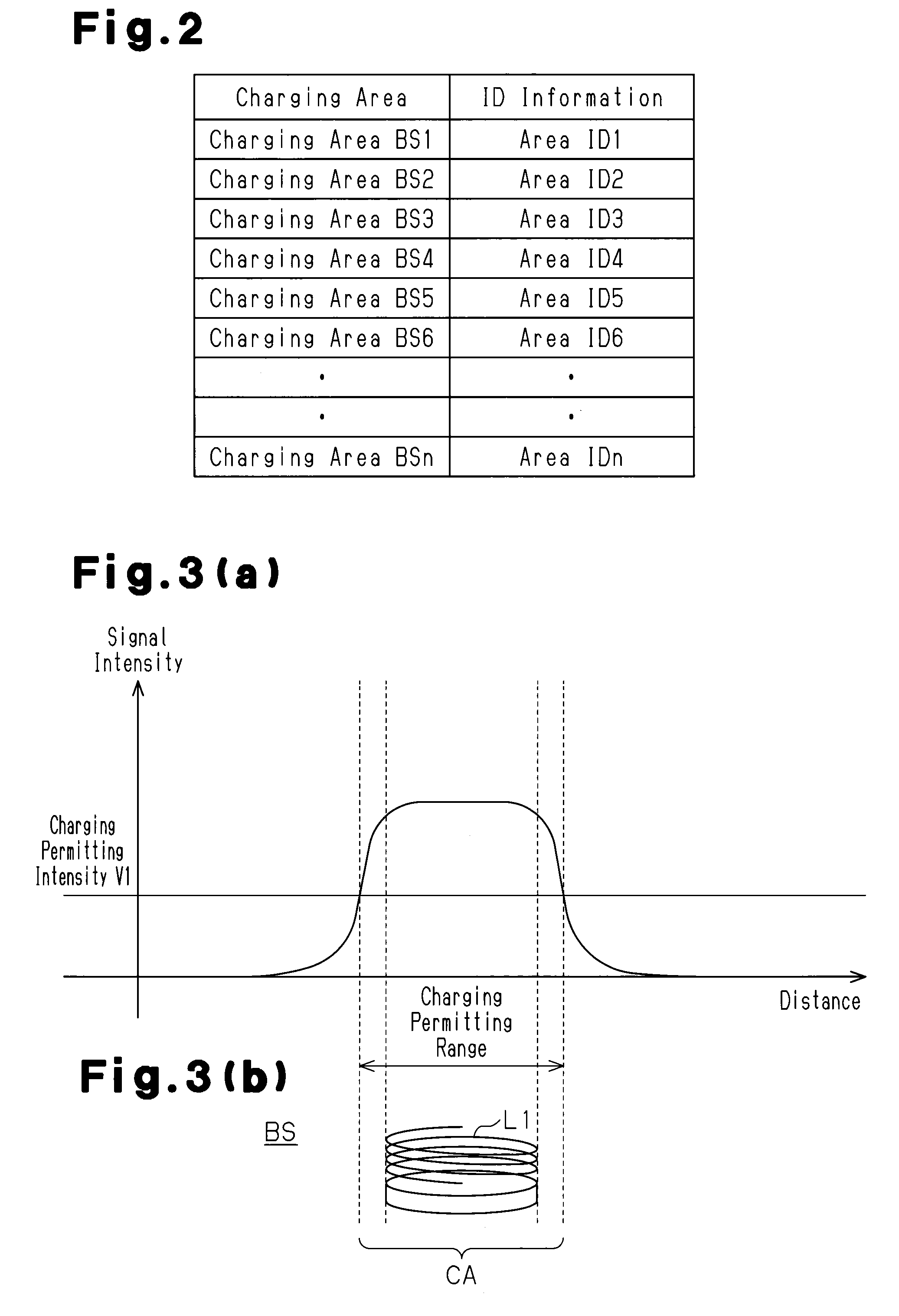
[0077]The charging apparatus 100 has an area ID assigning section 110 for assigning area IDs, which are information for determining the presence of the vehicle 200, to respective charging areas BS each for receiving the vehicle 200. The area ID assigning section 110 includes an a...

second embodiment

[0130]A second embodiment of the non-contact charging system, the non-contact charging method, the non-contact charging type vehicle, and the non-contact charging management apparatus according to the present invention will now be described with reference to FIG. 8. The second embodiment has a management center 300 for remotely managing the area IDs additionally to the first embodiment. The basic configuration of the second embodiment is identical to the configuration of the first embodiment.

[0131]FIG. 8 is a diagram corresponding to FIGS. 1 and 5, schematically representing the non-contact charging system of the second embodiment. The same or like reference numerals are given to components shown in FIG. 8 that are the same as or like corresponding components shown in FIG. 1 or 5 and repeated description of these components are omitted herein.

[0132]With reference to FIG. 8, a charging apparatus 100A of the second embodiment is configured by a plurality of charging stations ST1, ST2,...


PUM

PropertyMeasurementUnit
electric poweraaaaaaaaaa
areaaaaaaaaaaa
electricaaaaaaaaaa

Abstract

A charging apparatus assigns an area ID, which is information that the charging apparatus uses to determine the presence of a vehicle, to a charging area BS and transmits the assigned area ID. Based on return of the transmitted area ID from the vehicle 200, the charging apparatus establishes pairing, which is a communication connection setting, between the charging apparatus and the vehicle. The charging apparatus then performs electric power management of the electric power transmitted from the charging area BS to the vehicle in a non-contact manner through wireless communication between the paired vehicle and charging apparatus.

Description

FIELD OF THE DISCLOSURE[0001]The present invention relates to a non-contact charging system, a non-contact charging method, a non-contact charging type vehicle, and a non-contact charging management apparatus.BACKGROUND OF THE DISCLOSURE[0002]Recent electric vehicles and hybrid vehicles employ a storage battery serving as an electric power supply unit for an electric motor, which is a drive source for such vehicles. As a system for recharging such a storage battery, a charging system having a charging device for supplying electric power to the storage battery, such as a charging station, has been proposed. Specifically, to recharge the storage battery using the system, a feeding plug, which is attached to a distal end of an electric power supply cable extending from the charging device, is inserted into a feeding port formed in the vehicle. This electrically connects the feeding plug to the storage battery in the vehicle. The storage battery is thus recharged by supplying electric p...

Claims


Application Information

Patent Timeline
Patent Type & Authority Patents(United States)
IPC IPC(8): H02J7/00H01F38/14H02J7/02B60L3/12B60L11/18H02J5/00
CPCH02J7/025B60L3/12B60L11/182B60L11/1824B60L11/1831B60L11/1833B60L11/1846H02J5/005B60L2210/30Y02T10/7005Y02T10/7088Y02T10/7241Y02T90/121Y02T90/122Y02T90/125Y02T90/127Y02T90/128Y02T90/14Y02T90/16Y02T90/163Y02T90/169Y04S30/14Y02T10/7072B60L53/30B60L53/39B60L53/36B60L53/65H02J2310/48H02J50/10H02J50/80H02J50/90H02J7/00034B60L53/68B60L53/126Y02T10/70Y02T10/72Y02T90/12Y02T90/167Y04S30/12H02J50/12
Inventor SAGATA, KOJI
Owner TOYOTA JIDOSHA KK
Why Eureka
Try Eureka