Universal safety drain and method

Active Publication Date: 2015-12-01
PENTAIR WATER POOL & SPA INC
View PDF21 Cites 3 Cited by
  • Summary
  • Abstract
  • Description
  • Claims
  • Application Information

AI Technical Summary

Benefits of technology

The present invention provides a safety drain that can be used in most installations and accommodate increased water volume flow while preventing entrapment. It includes a base with a plurality of drain outlets and a cover that forms an input slot for water to enter the enclosure. A safety bridge is strategically placed in the enclosure to prevent entrapment even if the cover is removed. The drain is made of materials that provide ultraviolet radiation protection and is adaptable for use with different types of pool surfaces. A construction cover is removably installed to protect the drain during installation and can be reinstalled during installation.

Problems solved by technology

Various pool systems have incorporated many variations on this circulation system; however, several problems have persisted.
In this manner, a swimmer coming in contact with one of the drains and creating what otherwise would be a serious or fatal drain contact, will merely cause the flow rate through the remaining or uncovered drain to increase.
The inclusion of multiple drains, however, incorporates significant additional costs in the manufacture of a pool and particularly increases the cost of pool installation.
The added requirement for water flow volume caused by the added features increases the flow volume through the drain thus significantly increase the difficulties concerning entrapment.

Method used


Image

  • Universal safety drain and method
  • Universal safety drain and method
  • Universal safety drain and method

Examples


Embodiment Construction

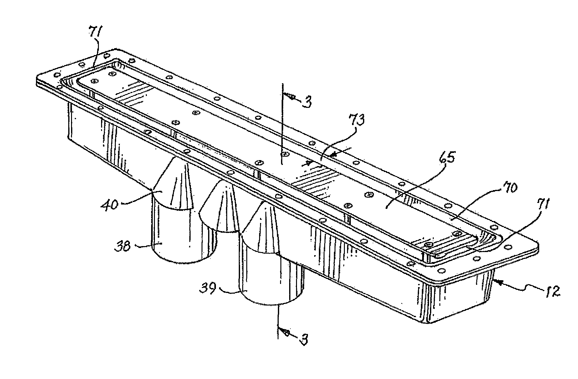
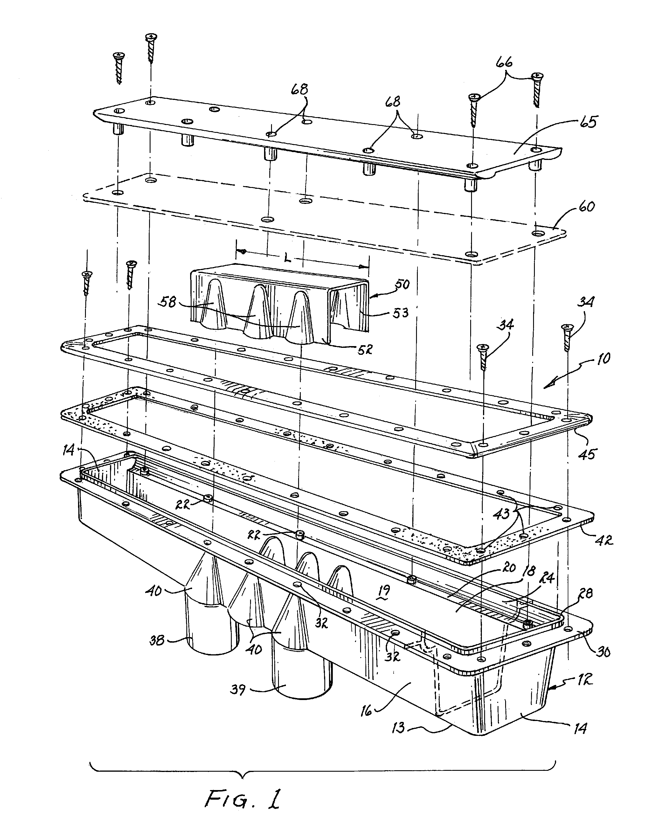
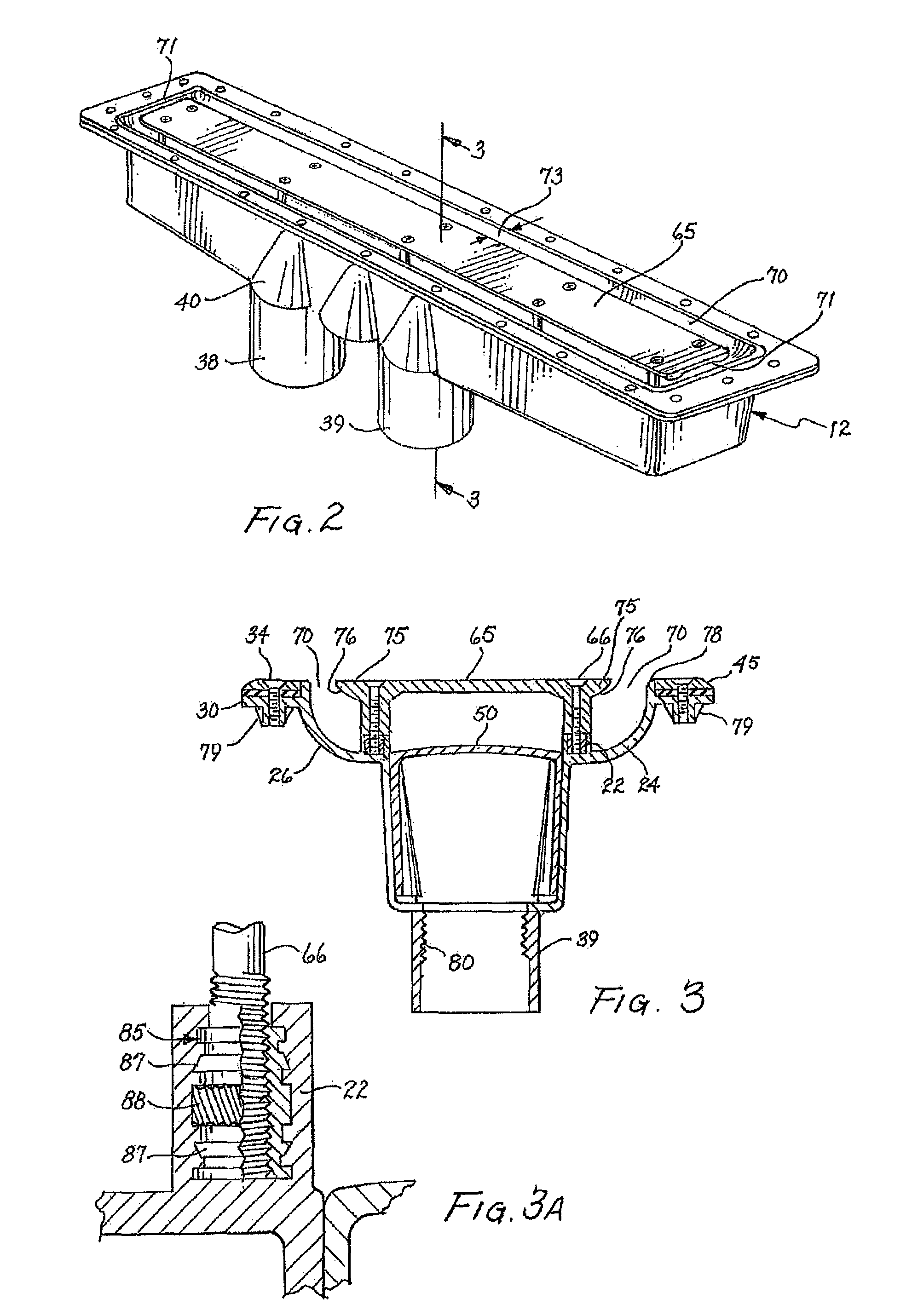
[0019]FIG. 1 is an exploded view of a safety drain 10 constructed in accordance with the teachings of the present invention. The drain incorporates a base 12, having a bottom 13, end walls 14 and having sidewalls 16 and 18 forming an open top enclosure 19 for receiving water from the pool. The sidewalls are upwardly diverging and form a horizontally extending support ledge 20. The ledge includes upwardly extending stanchions 22 strategically placed along the ledge. The walls continue past the ledge to upwardly curved lips 24 and 26 terminating in a vertically extending circumscribing rim 28. The walls continue from the rim 28 to a circumscribing horizontally extending flange 30. The flange is provided with a plurality of holes 32 to admit flange screws 34 for securing other portions of the drain. The base is formed of one-piece plastic material except for the drain attachments or fittings 38 and 39 which may be separately formed and subsequently cemented in place as shown. The upwar...


PUM


Abstract

A swimming pool safety drain including a base having a bottom, and having end walls and side walls extending upwardly from the bottom to form an open top enclosure. A cover is removably secured to the enclosure and, when secured to the enclosure forms an inlet slot about the periphery thereof. A plurality of drain outlets are formed in the base for connection to water recirculating systems for the swimming pool and any supplemental water recirculating system. A safety bridge is secured in the enclosure between the side walls and is positioned over the drain outlets to provide hair and limb entrapment protection. A construction cover is provided to temporarily replace the permanent cover during construction and installation of the drain.

Description

CROSS-REFERENCE TO RELATED APPLICATION[0001]This application is a continuation-in-part of a patent application entitled “ANTI-ENTRAPMENT, ANTI-VORTEX SAFETY DRAIN” filed May 25, 2006, now abandoned and assigned Ser. No. 11 / 440,478.FIELD OF THE INVENTION[0002]The present invention pertains to swimming pool drains, and particularly to swimming pool drains that are configured to provide protection against limb and hair entrapment. The invention is also directed to swimming pool drains that permit the increased flow rates resulting from added water features frequently accompanying swimming pools while maintaining protection against entrapment.BACKGROUND OF THE INVENTION[0003]This invention relates to swimming pools and more particularly to swimming pool drains that are designed to prevent entrapment while accommodating high water flow volume that may be encountered in modern swimming pools. Pool water circulating systems circulate and filter significant quantities of water; water is rem...

Claims


Application Information

Patent Timeline
IPC IPC(8): E04H4/00
CPCE04H4/00E04H4/1218
Inventor BLAKE, ANDY F.SUTTON, III, SAMUEL J.
Owner PENTAIR WATER POOL & SPA INC
Why Eureka
Try Eureka