Hydrating a fuel cell

Active Publication Date: 2013-06-13
AUDI AG
View PDF7 Cites 0 Cited by
  • Summary
  • Abstract
  • Description
  • Claims
  • Application Information

AI Technical Summary

Benefits of technology

The patent text describes methods and devices for controlling fluid distribution in fuel cells. The technical effect is that the methods and devices improve the performance and efficiency of fuel cells by optimizing water distribution within the cells and adjusting the volumetric flow of reactants and oxidants. This results in higher fuel utilization, reduced water usage, and increased power output.

Problems solved by technology

The conductivity of polymer electrolytes decreases as the humidity of air entering the fuel cell decreases, which can affect the performance and durability of the fuel cell.

Method used


Image

  • Hydrating a fuel cell
  • Hydrating a fuel cell
  • Hydrating a fuel cell

Examples


Embodiment Construction

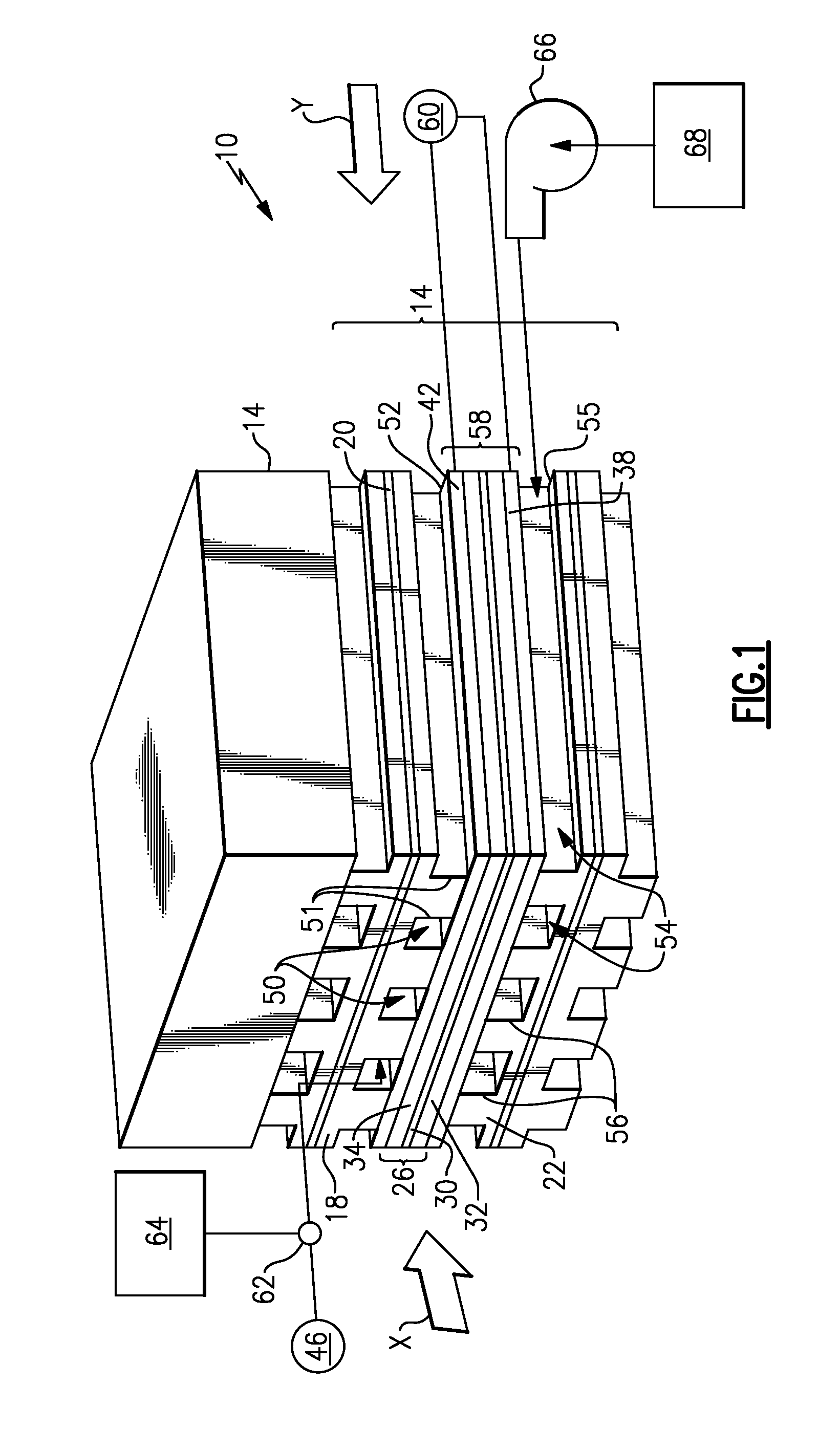
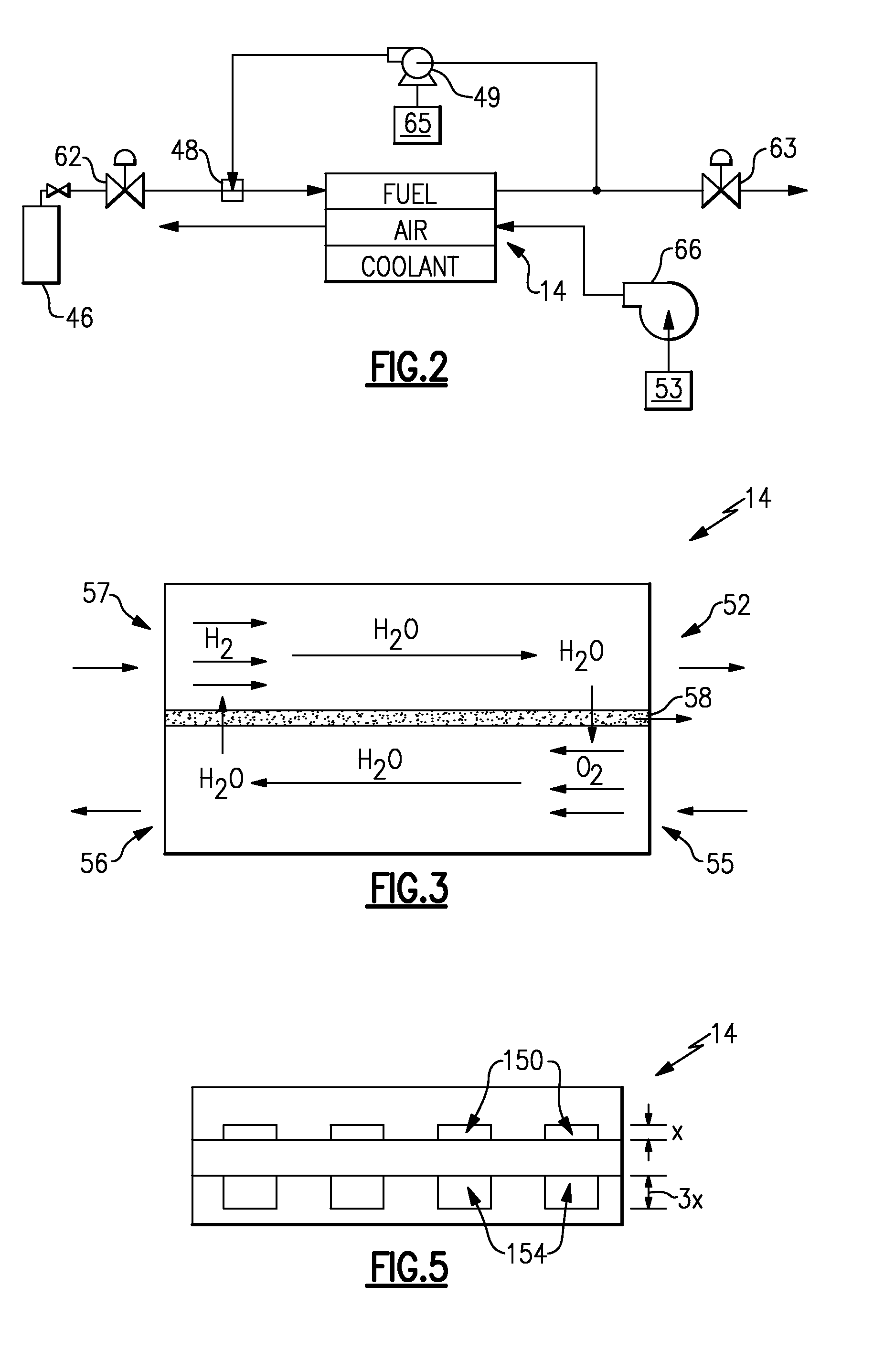
[0015]Referring to FIG. 1, an example proton exchange membrane fuel cell 10 includes multiple individual fuel cells 14 arranged in a stack. Each fuel cell 14 includes an anode plate 18 and a cathode plate 22 on opposing sides of a membrane electrode assembly 26. The membrane electrode assembly 26 includes a proton exchange membrane 30 positioned between catalyst layers 32 and 34. The typical cell package, as shown, has a solid separator plate 20 between the anode plate 18 and cathode plate 22. The solid plate 20 may be a separate element or it may be an integral part of either 18 or 22. While not shown for clarity reason each cell or number of cells may include a cooler plate.

[0016]A cathode side gas diffusion layer 38 is arranged between the cathode plate 22 and the membrane electrode assembly 26. The membrane electrode assembly 26 includes the anode catalyst layer 34, the proton exchange membrane 30, and the cathode catalyst layer 32. An anode side gas diffusion layer 42 is arrang...


PUM


Abstract

An example method of controlling fluid distribution within a fuel cell includes adjusting a flow of a reactant moving within a fuel cell to increase water within a portion of the fuel cell. Another example method of controlling fluid distribution within a fuel cell includes adjusting a flow of fuel entering a fuel cell, a velocity of air entering the fuel cell, or both, so that a first amount of water exiting the fuel cell in a fuel stream is about the same as a second amount of water exiting the fuel cell in an airstream.

Description

CROSS-REFERENCE TO RELATED APPLICATIONS [0001]This application is the U.S. national phase of PCT / US2010 / 047202, filed Aug. 31, 2010.TECHNICAL FIELD [0002]This disclosure relates generally to fuel cells. In particular, this disclosure relates to hydrating a fuel cell.DESCRIPTION OF RELATED ART [0003]Fuel cell assemblies and power plants are well known. One example fuel cell assembly includes multiple individual fuel cells arranged in a stack. Each individual fuel cell has an anode and a cathode positioned on either side of a polymer electrolyte membrane. A fuel, such as hydrogen, is supplied to the anode side of the polymer electrolyte membrane. An oxidant, such as air, is supplied to the cathode side of the polymer electrolyte membrane. The fuel and the oxidant initially move through channels established within plates. Gas diffusion layers distribute some of the hydrogen and the air from the channels to other portions of the fuel cell. Molecules of the hydrogen are oxidized in the c...

Claims


Application Information

Patent Timeline
IPC IPC(8): H01M8/04
CPCH01M8/026H01M8/04097H01M8/04291Y02E60/521H01M8/1002H01M8/04082H01M8/04753H01M8/1007Y02E60/50
Inventor MITTAL, VISHAL ONKARMALDARLING, ROBERT MASON
Owner AUDI AG
Why Eureka
Try Eureka