
Combined turbine expansion machine

A turboexpander, a composite technology, applied in the field of expanders, can solve the problems of difficult realization of multi-stage and power, high bearing and transmission requirements, large radial size, etc., and achieves simple structure, stable operation, and small flow loss. Effect

Inactive Publication Date: 2008-09-17
冀江 +1
View PDF0 Cites 13 Cited by
  • Summary
  • Abstract
  • Description
  • Claims
  • Application Information

AI Technical Summary

Problems solved by technology

Its disadvantages are: large radial size, high speed, high requirements for bearings and transmission, multi-stage and high power are not easy to achieve, etc.
[0008] 3. The structure layout must be very compact

Method used


Image

  • Combined turbine expansion machine
  • Combined turbine expansion machine
  • Combined turbine expansion machine

Examples


Embodiment Construction

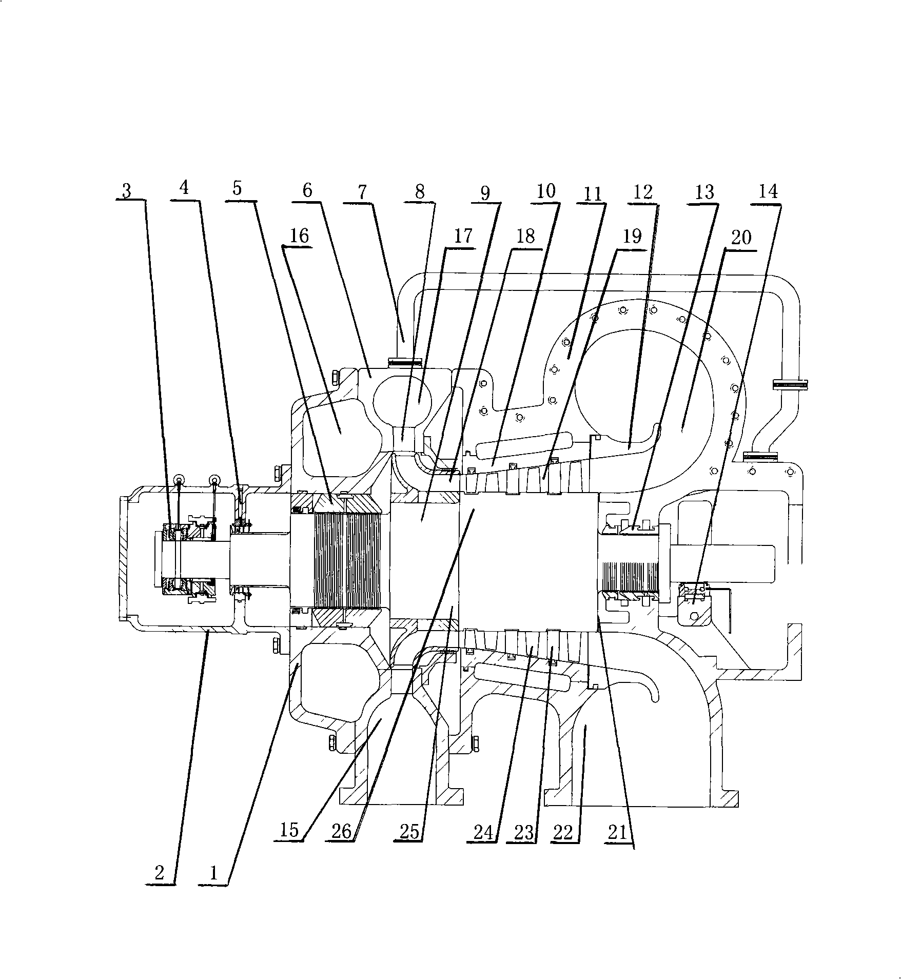
[0014] The structural principle and working principle of the present invention will be further described in detail below in conjunction with the accompanying drawings.

[0015] Referring to the accompanying drawings, a compound turboexpander includes a rotor 9, which is installed in a casing composed of a high-pressure section casing 6 and a low-pressure side casing 11, and the two ends of the rotor 9 are respectively supported by thrust bearings 3 Supported by support bearing 14, support thrust bearing 3 is installed in bearing box 2, and oil seal 4 is also arranged in bearing box 2, bearing box 2 is connected with end cover 1 through bolts, and end cover 1 is connected with high-pressure section through bolts The casing 6 is connected, and a high-pressure side shaft end seal 5 is arranged between the rotor 9 and the end cover 1. An inlet pipe 15 and an inlet volute 17 are arranged on the high-pressure section casing 6. The inlet pipe 15, the inlet volute 17 communicates with...


PUM


Abstract

The invention provides a composite turboexpander, which comprises a rotor. The rotor is arranged in a shell consisting of a high-pressure section casing and a low-pressure section casing; the high-pressure section casing is provided with an inlet pipe, and the inlet pipe communicates with an adjustable nozzle through a volute chamber; the high-pressure section of the rotor is provided with a radial impeller that communicates with the adjustable nozzle; the low-pressure section casing is provided with a blade carrier cylinder; the outlet of the blade carrier cylinder is provided with a flow deflecting ring, and the blade carrier cylinder is provided with a static blade; the low-pressure section casing is also provided with a volute chamber for exhausting and a vent-pipe; the low-pressure section of the rotor is provided with a moving blade; an axial flow stage comprises a first-stage static blade and a first-stage moving blade and communicates with the radial impeller and the flow deflecting ring; the pressure of the working medium decreases after going through the first-stage endocentric grade, the circumferential direction is changed into axial direction after the volume flow rate increases, and the axial flow stage is finally reached. The composite turboexpander has the advantages of simple structure, small volume flow rate for first-stage entry, high expansion rate, high expanding efficiency, convenient installation and maintenance, steady operation, etc.

Description

technical field [0001] The invention relates to the technical field of expanders, in particular to a compound turbo expander. Background technique [0002] The turbo expander converts energy by using the change in velocity when the working fluid flows. The working fluid expands in the flow-through part of the turboexpander to obtain kinetic energy, and the external work is output from the working wheel shaft, thus reducing the internal energy and temperature of the outlet working fluid. In contemporary industry, turboexpanders are mainly used for refrigeration and energy recovery. According to the flow direction of the working fluid in the turboexpander, there are mainly two types: radial flow and axial flow. According to the flow direction of the working fluid from the outer circumference to the center or from the center to the outer circumference, the radial flow type has a centripetal type and a centrifugal type. Due to the high flow losses of centrifugal impellers, on...

Claims


Application Information

Patent Timeline
Patent Type & Authority Applications(China)
IPC IPC(8): F01D1/02F01D5/02F01D5/10F01D25/00
Inventor 冀江史哓云
Owner 冀江
Learn More