Fan volute intermediate plate guide vane air inlet structure of smoke exhaust ventilator

A technology of range hood and air intake structure, applied in the direction of machine/engine, mechanical equipment, liquid fuel engine, etc., can solve the problems of increasing noise, increasing energy consumption, increasing the outer diameter of the volute, etc., to achieve efficiency The effect of improving and increasing the air volume

Inactive Publication Date: 2013-02-20
SHENGZHOU YUANJIAN MACHINERY TECH
View PDF4 Cites 3 Cited by
  • Summary
  • Abstract
  • Description
  • Claims
  • Application Information

AI Technical Summary

Problems solved by technology

[0006] According to the current existing technology, to increase the suction and discharge capacity of the volute centrifugal fan, the following methods have to be solved: 1. Increase the power of the motor; 2. Increase the outer diameter of the impeller, the width of the impeller blade and the height of the impeller, and increase The outer diameter of the volute, although the above method has improved the suction and discharge capacity of the range hood, but the actual technical problems brought about are the increase in the volume of the fan, the increase in energy consumption, and the increase in noise at the same time

Method used


Image

  • Fan volute intermediate plate guide vane air inlet structure of smoke exhaust ventilator
  • Fan volute intermediate plate guide vane air inlet structure of smoke exhaust ventilator
  • Fan volute intermediate plate guide vane air inlet structure of smoke exhaust ventilator

Examples


Embodiment Construction

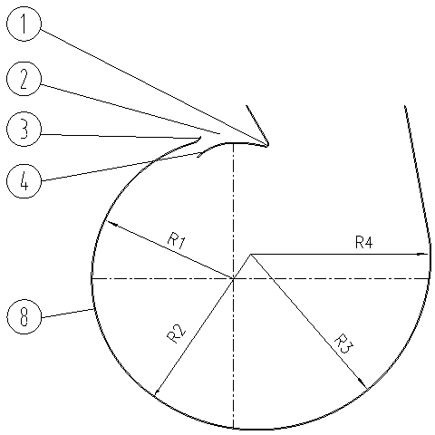
[0017] see figure 1 The guide vane inlet structure of the fan volute middle plate of the range hood includes an annular middle plate 8 that can be connected with the front cover plate and the rear cover plate of the volute, and the volute tongue 1 angle on the annular middle plate 8 is designed to prevent The air volume does not enter the outlet and re-flows to the volute. The rear end of the volute tongue 1 is provided with an air inlet 2.

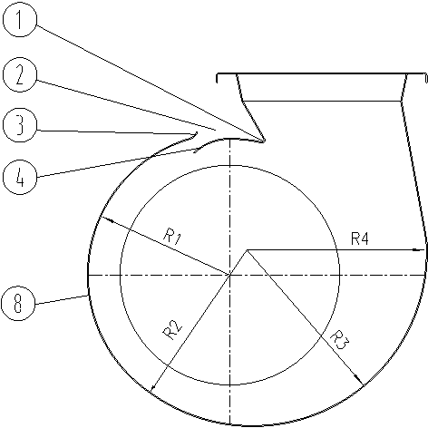
[0018] see figure 2 ; The central arc of the volute R2 is the same size as the central arc of R1, without arc displacement, so that the volume of the volute can be made smaller.

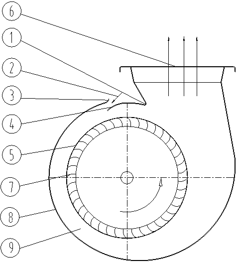
[0019] see image 3 The rear end of the volute tongue 1 at the front end of the annular middle plate 8 has an air inlet 2, so that after the fan blade 7 of the impeller 5 passes through the volute tongue 1, the airflow is introduced from the air inlet 2 through the air inlet deflector 4 immediately, so that the efficiency of the fan is improved , the air vol...


PUM


Abstract

The invention discloses a fan volute intermediate plate guide vane air inlet structure of a smoke exhaust ventilator. The technical scheme is that the fan volute intermediate plate guide vane air inlet structure of the smoke exhaust ventilator comprises an annular intermediate plate which is connected with a front cover plate and a rear cover plate of a volute; the angle of a volute tongue at the front end of the annular intermediate plate is designed as an angle which prevents air flow from flowing into an outlet and enables the air flow to flow into the volute; an air inlet is formed in the rear end of the volute tongue; another air inlet is formed in the rear end of the volute tongue of the annular intermediate plate, and thus a fan blade of an impellor can guide-in the air flow from the air inlet through an air inlet flow guide plate, and the fan efficiency is improved; the air amount at an outlet is increased; certain distance is left between the front end of a flow guide plate and the rear end of the an air defector, and thus air is extremely easy to guide into the volute; and while the flowing air flow in the volute is shielded due to the length of the air inlet flow guide plate, under the directional rotation of the impellor, the air flow can not flow out of the air inlets, the air is guide-in from the air inlets to be directly transmitted to the air outlet of the volute through an outer angle of a impellor fan blade, the air flow friction loss of the impellor at a channel is reduced, and thus the air pressure and the air speed of the fan are improved.

Description

technical field [0001] The invention relates to an air intake structure of a volute case of a range hood, in particular to an air intake structure of a fan volute intermediate plate guide vane of the range hood. Background technique [0002] The range hood is one of the indispensable kitchen appliances in the family. It is known that various household range hoods can be divided into three categories, 1 near-suction type, 2 European type, and 3 integrated type. The core components of these types of range hoods are It is inseparable from the volute centrifugal fan. [0003] The volute of the volute centrifugal fan currently used on range hoods is composed of a front cover, a rear cover and an intermediate plate connecting the two. The impeller in the middle of the volute is connected to the motor and installed on the rear cover. There is an air inlet on the front cover. The working principle of this centrifugal fan is that the rotation of the motor drives the impeller connect...

Claims


Application Information

Patent Timeline
Patent Type & Authority Applications(China)
IPC IPC(8): F04D29/44
Inventor 胡国贤
Owner SHENGZHOU YUANJIAN MACHINERY TECH
Why Eureka
Try Eureka