Systems and methods for hydraulic lash adjustment in an internal combustion engine

a technology of hydraulic lash adjustment and internal combustion engine, which is applied in the direction of machines/engines, non-mechanical valves, valve arrangements, etc., can solve the problems of manual setting of lash, change size and shape, and inability to automatically adjust lash space between engine valves and valve actuation systems,

Active Publication Date: 2015-12-01
JACOBS VEHICLE SYST
View PDF16 Cites 9 Cited by
  • Summary
  • Abstract
  • Description
  • Claims
  • Application Information

AI Technical Summary

Problems solved by technology

Additionally, over the life of an engine, engine components may wear, and thus change size and shape.
Hydraulic lash adjustors, however, have not been used to automatically adjust lash space between an engine valve and a valve actuation system designed to provide both positive power and auxiliary engine valve events, such as engine braking events.
Manually setting lash may be a cumbersome and expensive process required both at the factory during manufacturing and in service.
For example, it is not uncommon for engine valve float to occur as the result of an over speed condition or high exhaust backpressure in the engine.
In such situations, a conventional hydraulic lash adjuster may “jack” by progressively locking excess hydraulic fluid in the lash adjustment circuit such that the engine valve at issue does not close properly even when the cam actuating it is at base circle.

Method used


Image

  • Systems and methods for hydraulic lash adjustment in an internal combustion engine
  • Systems and methods for hydraulic lash adjustment in an internal combustion engine
  • Systems and methods for hydraulic lash adjustment in an internal combustion engine

Examples


Embodiment Construction

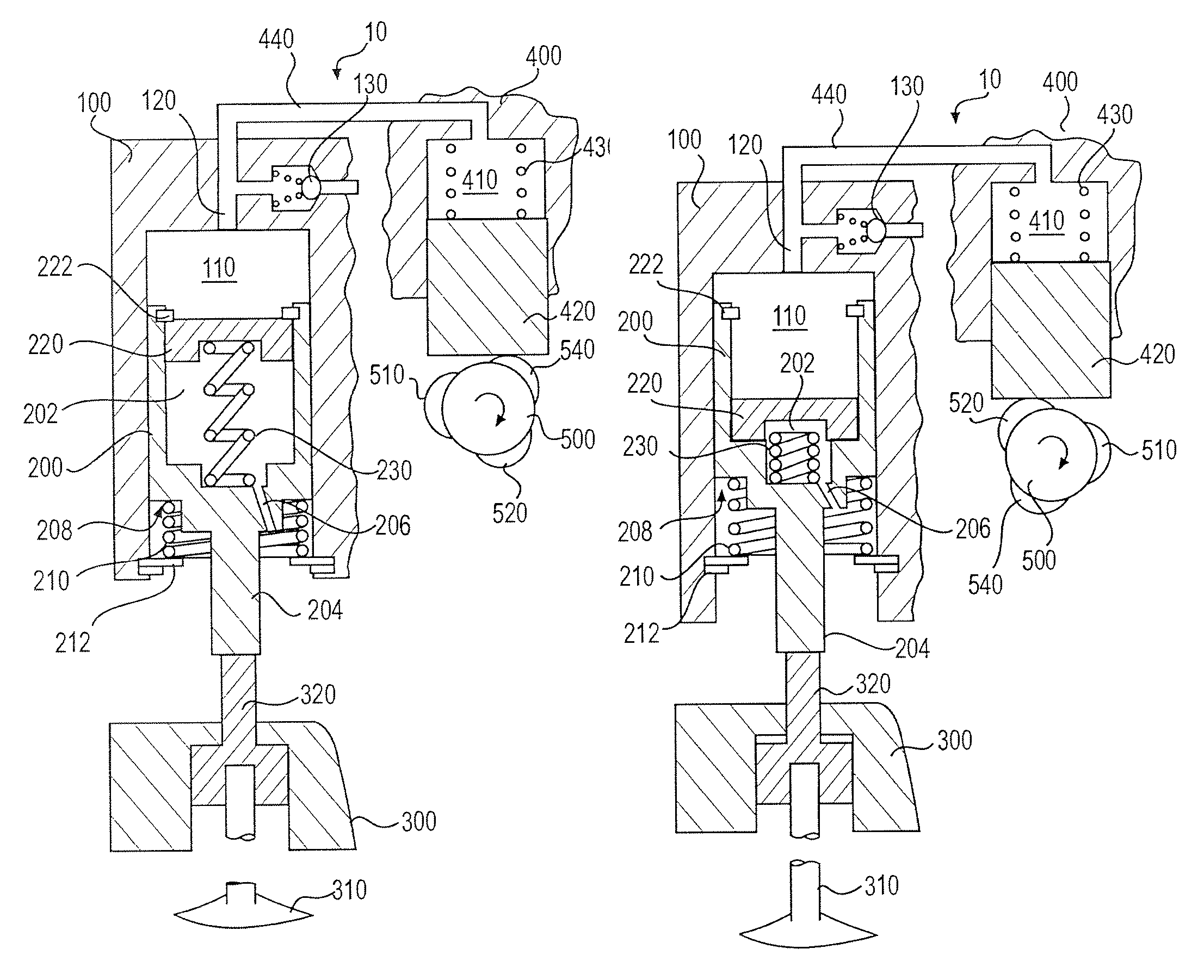
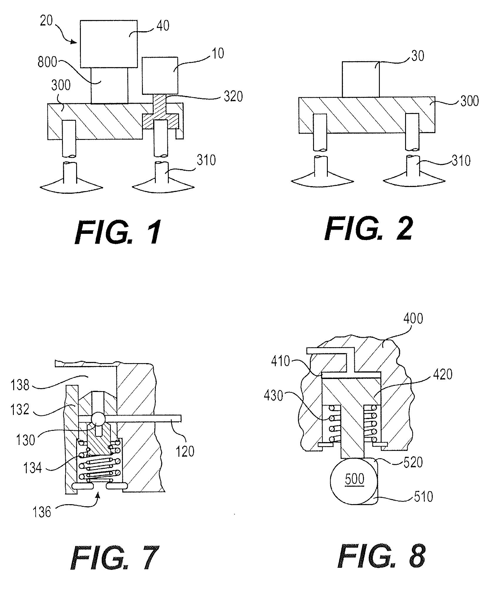
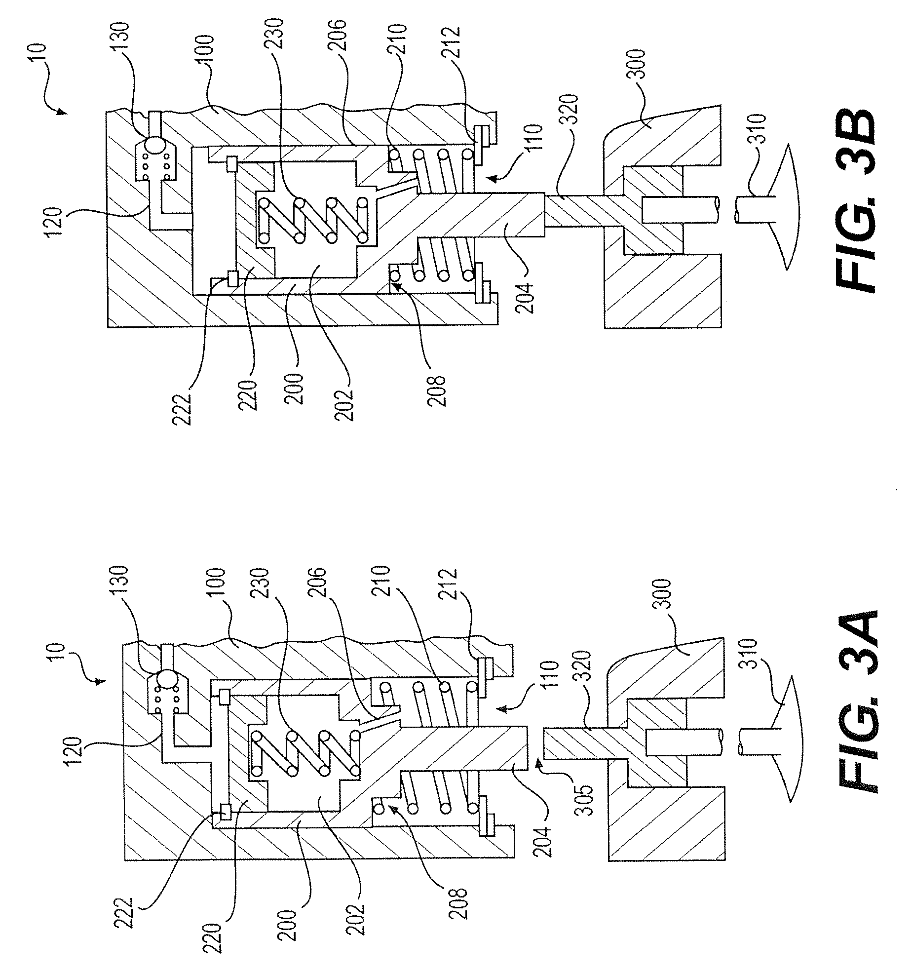
[0029]With reference to FIG. 1, in one or more embodiments of the present invention, two or more engine valves 310 may be connected by a valve bridge 300. A first valve actuation system 20 may be used to provide the engine valves with positive power valve actuation, such as main intake or main exhaust valve actuation. The first valve actuation system 20 may include one or more valve train elements, such as rocker arms, cams, push tubes and hydraulically adjusted components. A second valve actuation system 10 may be used to provide one of the engine valves 310 with auxiliary valve actuation motion, such as engine braking valve actuation. The second valve actuation system 10 may include a self-lashing hydraulic actuator which acts on a sliding pin 320 to actuate the engine valve 310 while also automatically adjusting lash space between the second valve actuation system and the sliding pin.

[0030]The first valve actuation system 20 may, optionally, include a hydraulic lash adjuster 800 ...


PUM


Abstract

Systems and methods for actuating engine valves for positive power and engine braking operation are disclosed. The systems may include a self-lashing hydraulic piston slidably disposed in a fixed or rocker arm housing. The hydraulic piston may have an internal cavity in which a motion absorbing piston is disposed. A hydraulic fluid source may communicate with the hydraulic piston bore. A check valve which may be incorporated in a control valve may controls hydraulic fluid supply from the hydraulic fluid source to the hydraulic piston to provide self-lashing operation of the valve actuation system.

Description

CROSS REFERENCE TO RELATED APPLICATIONS[0001]This application relates to, and claims the benefit of the earlier filing date and priority of U.S. Patent Application No. 61 / 674,063, filed Jul. 20, 2012, and entitled “SYSTEMS AND METHODS FOR HYDRAULIC LASH ADJUSTMENT IN AN INTERNAL COMBUSTION ENGINE.”FIELD OF THE INVENTION[0002]The present invention relates to systems and methods for hydraulically adjusting lash space between engine poppet valves and actuators therefore in internal combustion engines.BACKGROUND OF THE INVENTION[0003]Internal combustion engines typically use either a mechanical, electrical, or hydro-mechanical valve actuation system to actuate the engine valves. These systems may include a combination of camshafts, rocker arms and push rods that are driven by the engine's crankshaft rotation. When a camshaft is used to actuate the engine valves, the timing of the valve actuation may be fixed by the size and location of the lobes on the camshaft.[0004]For each 360 degree...

Claims


Application Information

Patent Timeline
Patent Type & Authority Patents(United States)
IPC IPC(8): F01L1/18F01L9/02F01L13/06F01L9/12
CPCF01L1/18F01L13/06F01L9/023F01L2800/10F01L9/12
Inventor ROBERTS, GABRIEL SCOTTBALTRUCKI, JUSTIN DAMIENAUDIBERT, KEVIN
Owner JACOBS VEHICLE SYST
Why Eureka
Try Eureka