Differential gear provided with differential lock mechanism

a technology of differential lock mechanism and differential gear, which is applied in the direction of machine/engine, transportation and packaging, etc., can solve the problems of complex structure and large volume of the differential gear provided with the differential lock mechanism, and achieve the effect of suppressing the increase in the size of the gear casing and enhancing maintenability

Active Publication Date: 2015-12-01
HONDA MOTOR CO LTD
View PDF8 Cites 6 Cited by
  • Summary
  • Abstract
  • Description
  • Claims
  • Application Information

AI Technical Summary

Benefits of technology

[0026]In the first aspect, the collecting member and the collecting transmission member are interposed between the first and second cables and the switching means. The operation of the first cable and the operation of the second cable can be merged by the collecting member, and it is sufficient to connect only the collecting transmission member to the switching means. The connection between the switching means and the collecting transmission member becomes extremely simple thus miniaturizing the connection between the switching means and the collecting transmission member. As a result, it is possible to miniaturize the differential gear provided with a differential lock mechanism which is mechanically connected to two manipulators.
[0029]In the fourth aspect, the posture adjustment and the position adjustment of the collecting member and the adjustment of cable lengths can be collectively performed and hence, maintainability of the differential gear can be enhanced.
[0032]In the seventh aspect, in mounting the bearing which supports the cylindrical shaft and the rotary shaft which is rotated by the switching means on the gear casing, the rotary shaft is arranged in the vicinity of the bearing. Since the bearing and the rotary shaft are arranged close to each other, increase in size of the gear casing can be suppressed whereby the differential gear provided with a differential lock mechanism can be formed into a compact shape.
[0033]In the eighth aspect, by arranging the third cable between the casing and the differential mechanism, the casing can be arranged at a position away from the differential mechanism. The casing can be arranged at a relatively free position and hence, it is possible to enhance maintenability such as the adjustment of a play of the cable.
[0035]In the tenth aspect, the heat shield panel is arranged between the exhaust pipe and the switching means. Heat emitted to the switching means from the exhaust pipe can be shielded and hence, the switching means, which should be protected from dirt, can be covered by a dustproof cover made of a resin. That is, the third cable can be wired on an upper surface of the differential mechanism while preventing a thermal influence of the exhaust pipe. Due to the provision of the heat shield plate, the exhaust pipe and the switching means can be arranged close to each other and hence, accessories can be arranged on the vehicle in a compact manner.

Problems solved by technology

Since the structure has two connection portions, there is a tendency for the structure of a differential gear provided with a differential lock mechanism to become complicated and large.

Method used


Image

  • Differential gear provided with differential lock mechanism
  • Differential gear provided with differential lock mechanism
  • Differential gear provided with differential lock mechanism

Examples


Embodiment Construction

[0053]An embodiment of the invention is explained hereinafter by reference to attached drawings.

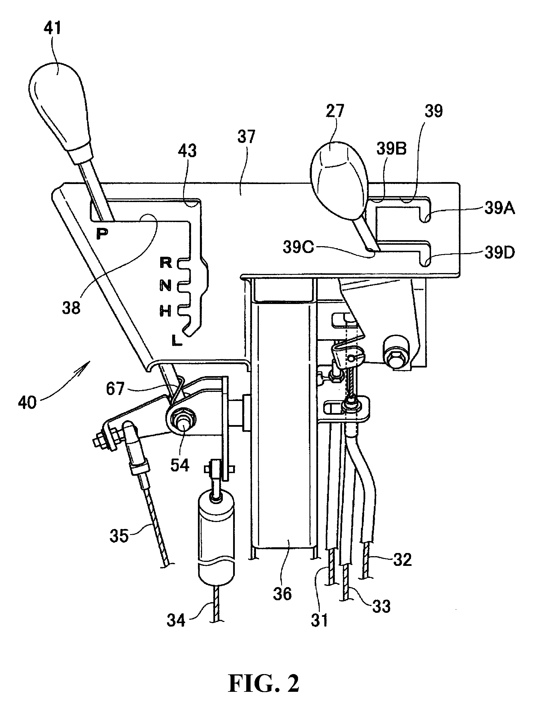
[0054]First and second manipulators are explained by reference to FIG. 1 to FIG. 6, and a differential gear provided with a differential lock mechanism according to the invention is explained in detail by reference to FIG. 7 and drawings which follow FIG. 7.

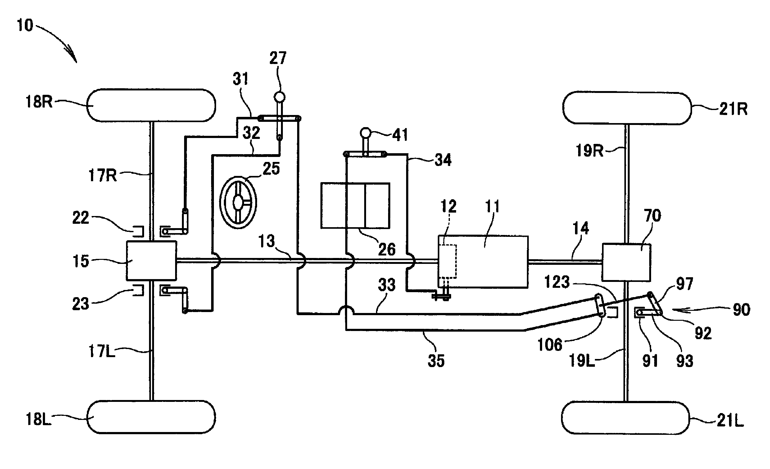
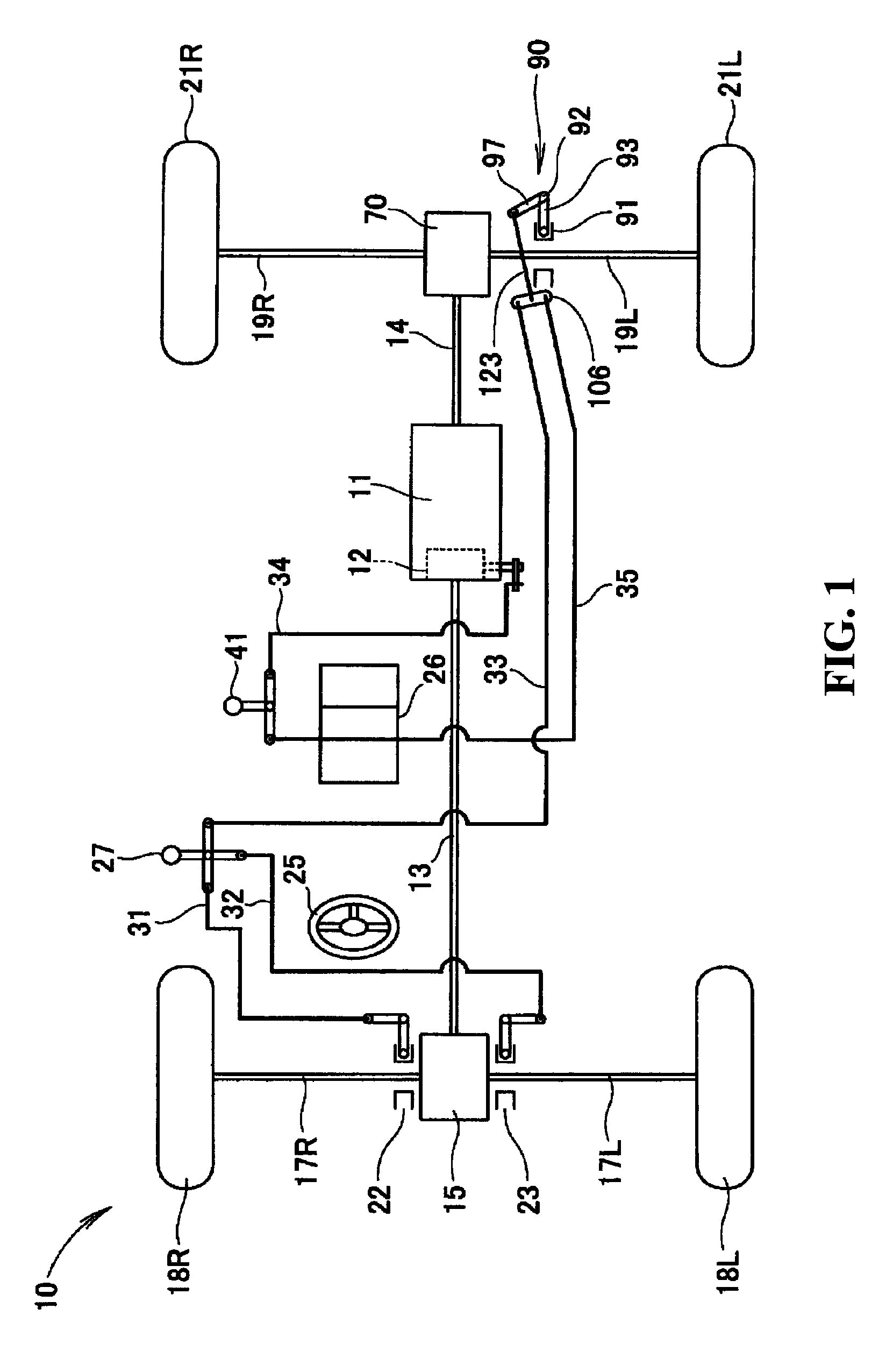
[0055]As shown in FIG. 1, a vehicle 10 includes: a power unit 11; a transmission 12 which transmits power of the power unit 11 with a speed change and is represented by a gear transmission; a front propeller shaft 13 and a rear propeller shaft 14 which extend frontward and rearward from the transmission 12 for transmission of power; a front differential gear 15 which distributes power transmitted through the front propeller shaft 13 to left and right sides; a differential gear 70 provided with a rear differential lock mechanism which distributes power transmitted through the rear propeller shaft 14 to left and right sides; front drive ...


PUM


Abstract

A differential mechanism regulating device which is mechanically connected to two manipulators is miniaturized. When a first cable and a second cable are pulled, a collecting member moves its position. As a result of this movement, the collecting member tilts a portion of an arm by way of a rod. As a result, a differential lock is released. The operation of the first cable and the operation of the second cable can be merged by the collecting member, and it is sufficient to connect only a collecting transmission member to the arm. The connection between the arm and the collecting transmission member can be simplified thus realizing the miniaturization of the differential mechanism.

Description

CROSS REFERENCE TO RELATED APPLICATIONS[0001]The present application claims priority under 35 U.S.C. §119 to Japanese Patent Application No. 2013-210205, filed Oct. 7, 2013, and Japanese Patent Application No. 2014-166167, filed Aug. 18, 2014, the contents of which are incorporated herein by reference, in their entirety.TECHNICAL FIELD[0002]The present invention relates to an improvement in a differential gear provided with a differential lock mechanism.BACKGROUND OF THE INVENTION[0003]A differential gear is a device for generating a difference in rotational speed between left and right wheels. There may be a case where it is necessary not to provide a difference in rotational speed between left and right wheels depending on a traveling state. In this case, a mechanism which regulates the differential gear (hereinafter referred to as a differential lock mechanism) is attached to the differential gear. Various proposals have been made with respect to such a differential gear provided...

Claims


Application Information

Patent Timeline
Patent Type & Authority Patents(United States)
IPC IPC(8): B60K17/354F16H48/30B60K23/04F16H59/10F16H61/36B60K23/08
CPCF16H48/30B60K23/04B60K17/352B60K17/354F16H2048/305B60K2023/0891F01N2340/04F16H59/10F16H61/36B60K2023/046
Inventor SATO, KOJIHAYAKAWA, KOSHI
Owner HONDA MOTOR CO LTD
Why Eureka
Try Eureka