
Image forming method and image forming device

a technology of image forming and forming device, which is applied in the field of image forming method, can solve the problems of increasing the amount of toner consumed per unit time for the development of electrostatic images, providing a large amount of dust, and not being compatible with a binder resin, so as to improve the hot offset resistance of graphic use, improve the effect of image quality and reduce the amount of dust during fixation

Active Publication Date: 2015-12-08
MITSUBISHI CHEM CORP
View PDF8 Cites 0 Cited by
  • Summary
  • Abstract
  • Description
  • Claims
  • Application Information

AI Technical Summary

Benefits of technology

The present invention improves image quality and resistance to hot offset when using a lot of toner for developing electrostatic images. It also reduces dust emission during fixation.

Problems solved by technology

Further, in high-speed printing, the amount of the toner to be consumed per unit time for development of electrostatic images increases, and therefore more volatile organic compounds and dust would be thereby diffused.
In general, wax having good releasability tends to provide a large amount of dust.
This is because, the wax that may readily bleed out of a binder resin during fixation is non-polar and is therefore non-compatible with a binder resin, or has a low molecular weight and therefore has a low melt viscosity.
On the contrary, those having polarity such as ester wax and the like, or high-molecular-weight waxes, and further those having a high content of unnormalized forms such as iso-form, cyclic form and the like of hydrocarbon waxes hardly bleed out during fixation owing to the above-mentioned intermolecular force and to entanglement of wax molecular chains, and in general, therefore, they tend to be relatively poor in releasability but they hardly sublime and the dust emission amount from them is small.

Method used


Image

  • Image forming method and image forming device
  • Image forming method and image forming device
  • Image forming method and image forming device

Examples


examples

[0151]The invention is described more concretely with reference to the following Examples; however, not overstepping the spirit and the scope thereof, the invention is not limited to the following Examples. In the following Examples, “part” is “part by weight”.

[0152]The particle size, the circularity and the electric conductivity were measured as follows.

[0153]The volume-average diameter (MV) of particles having a volume-average diameter (MV) of less than 1 micron was measured, using Nikkiso's Model, Microtrac Nanotrac 150 (hereinafter abbreviated as “Nanotrac”) and using the same company's analysis software Microtrac Particle Analyzer Ver. 10. 1.2.-019EE. The sample was analyzed according to the method described in the instruction manual and using ion-exchanged water having an electric conductivity of 0.5 μS / cm as a solvent, in which the solvent refractivity was 1.333, the measurement time was 600 seconds, the measurement time was 1 time. Regarding the other present conditions, the...


PUM


Abstract

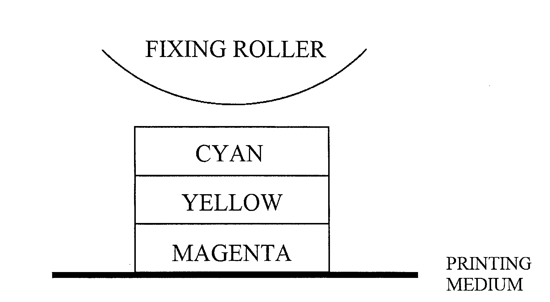
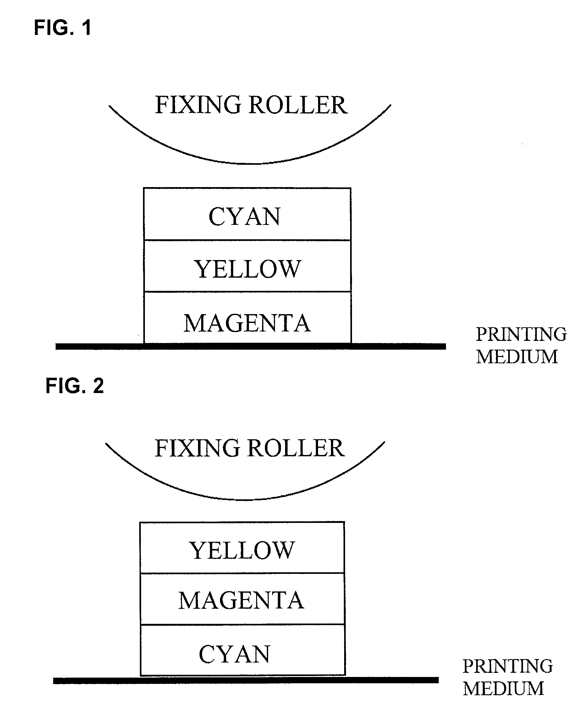
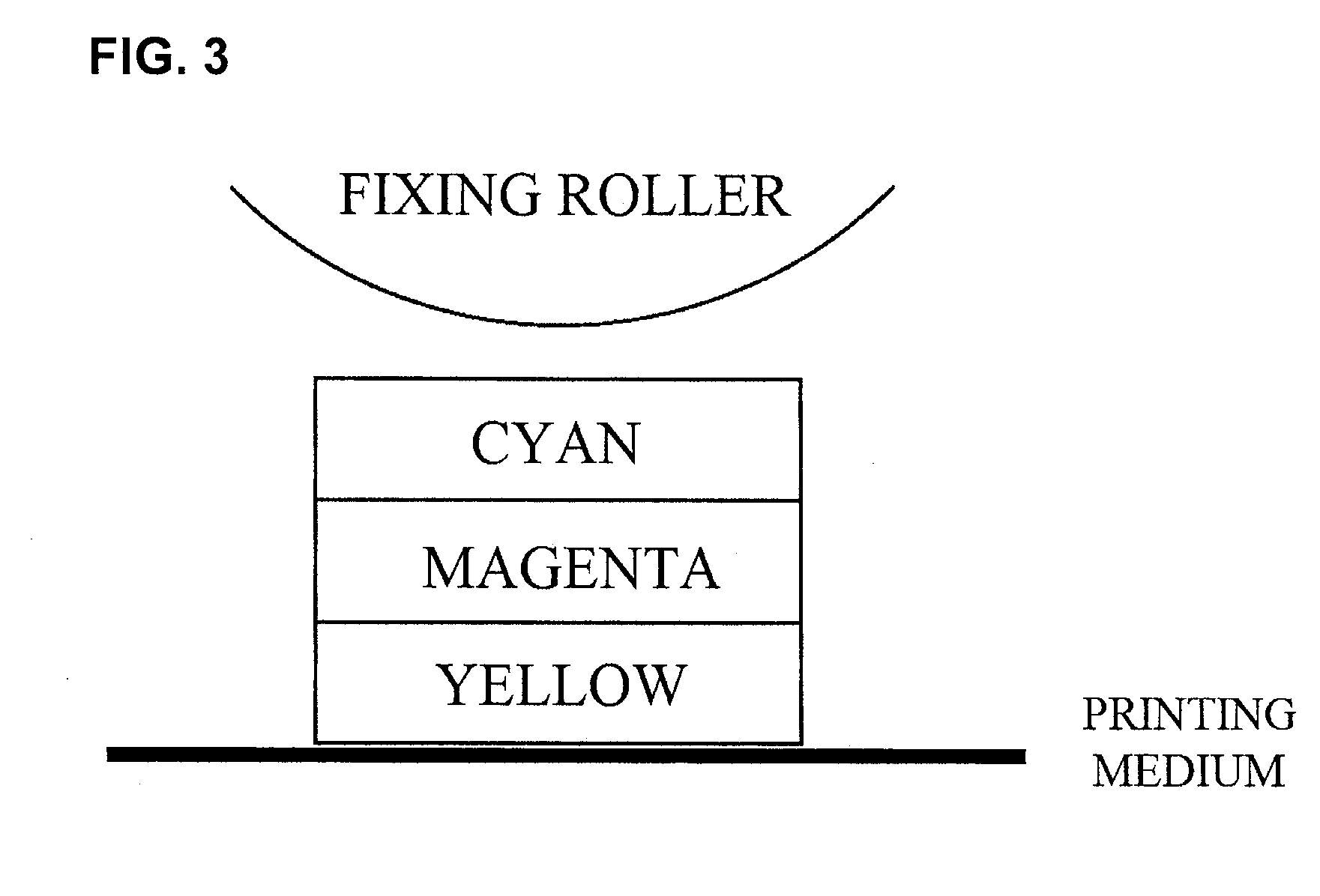
The invention relates to an image forming method and an image forming device using at least four color toners of yellow, magenta, cyan and black, and having a fixation step of fixing a toner image on a recording medium using a fixing unit, wherein the total of a dust emission amount from each toner is controlled to be not more than a specific level, and wherein just before the fixation step where the three color toners of yellow, magenta and cyan are laminated on the recording medium, a dust emission amount from the toner to be the outermost layer on the recording medium and a dust emission amount from the toner to be the lowermost layer thereon are controlled to be in a specific relationship therebetween.

Description

TECHNICAL FIELD[0001]The present invention relates to an image forming method for use in electrophotographic copiers and image forming devices, and to an image forming device using the method.BACKGROUND ART[0002]With the recent popularization of copiers, printers and the like, environmental regulations on human health in office environments have become established mainly in Europe. Further, in high-speed printing, the amount of the toner to be consumed per unit time for development of electrostatic images increases, and therefore more volatile organic compounds and dust would be thereby diffused.[0003]In addition, the arena of electrophotography is expanding not only in the field of letter printing for the past office use or the like but also in the field of graphic use for photographic printing and others, and the amount per sheet of the toner to be used for development of electrostatic images is increasing exponentially.[0004]With such changes in needs, calls to providing a toner ...

Claims


Application Information

Patent Timeline
Patent Type & Authority Patents(United States)
IPC IPC(8): G03G15/20G03G15/01G03G9/08
CPCG03G15/2014G03G15/01G03G9/08G03G15/0105G03G15/2075G03G2215/2074G03G2215/2083G03G15/0126G03G15/20G03G9/09G03G9/0821G03G9/08782G03G9/09392G03G15/2025
Inventor YASUTOMI, SHIRO
Owner MITSUBISHI CHEM CORP
Learn More