Downhole cable termination systems

Active Publication Date: 2015-12-08
SIEMENS ENERGY GLOBAL GMBH & CO KG
View PDF7 Cites 0 Cited by
  • Summary
  • Abstract
  • Description
  • Claims
  • Application Information

AI Technical Summary

Benefits of technology

[0010]The pressure in the downhole environment may fluctuate, for example, due to the operation of an electric submersible pump in the well. This pressure fluctuation may cause a problem for the elastomers that have absorbed gas. A rapid drop in pressure results in the gas that has permeated the elastomer rapidly expanding. The majority of the expanding gas absorbed into the material may be unable to diffuse to accommodate the expansion, and as a result, the gas expansion within the material may damage and tear the material. This effect is known as rapid gas decompression (RGD).
[0128]With this method, air may be removed from around the first part of the sleeve before the second part is joined. The second part of the sleeve may be joined to the first part of the sleeve under oil so that no air is trapped between the two parts when the two parts are joined together. This may minimize air trapped between the two components, which may reduce the problem of electrical discharges mentioned above.

Problems solved by technology

Such connectors in the tubing hanger are subjected to hostile conditions such as extreme temperatures and pressures and aggressive chemicals, and thus, the connectors are to be designed to deal with these conditions.

Method used


Image

  • Downhole cable termination systems
  • Downhole cable termination systems
  • Downhole cable termination systems

Examples


Embodiment Construction

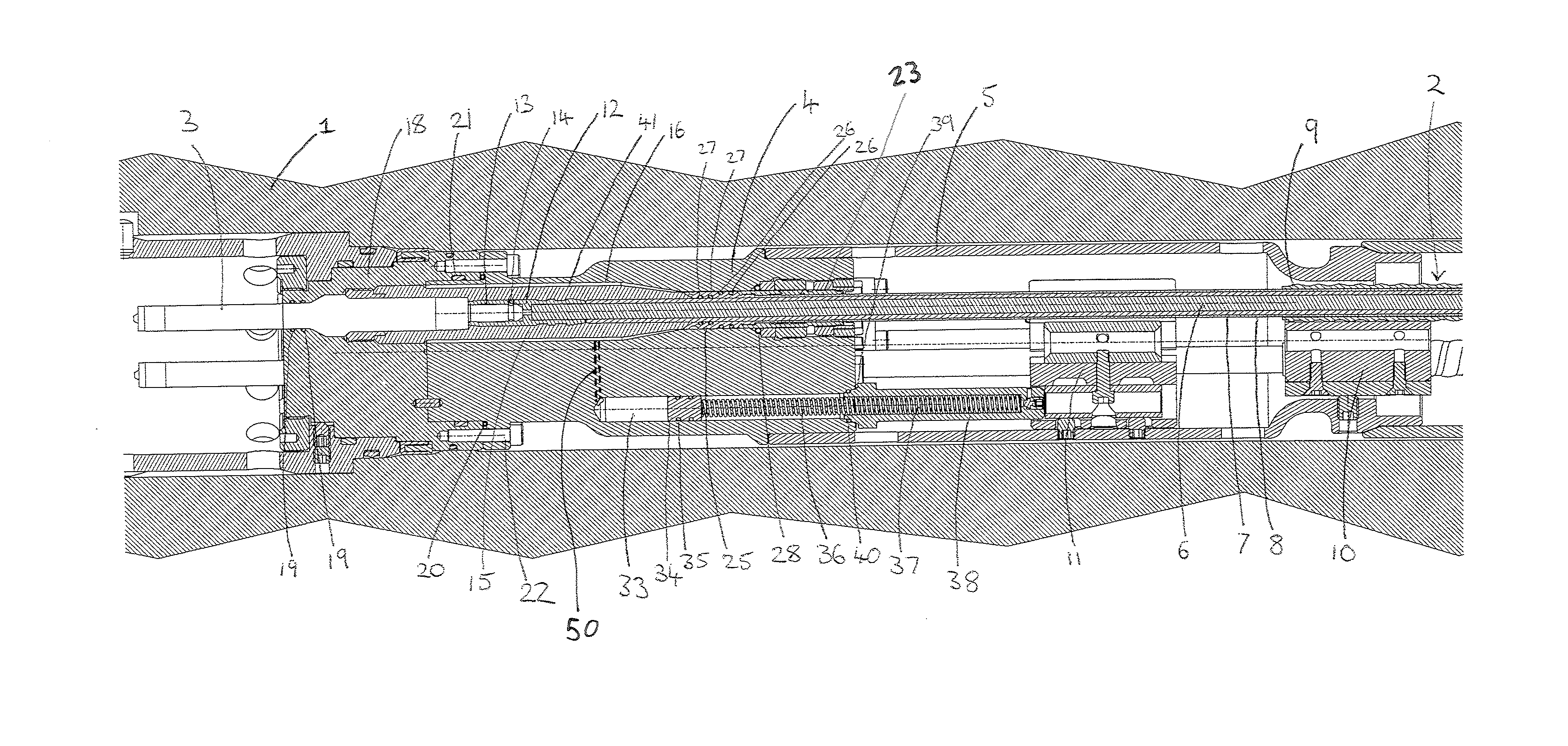
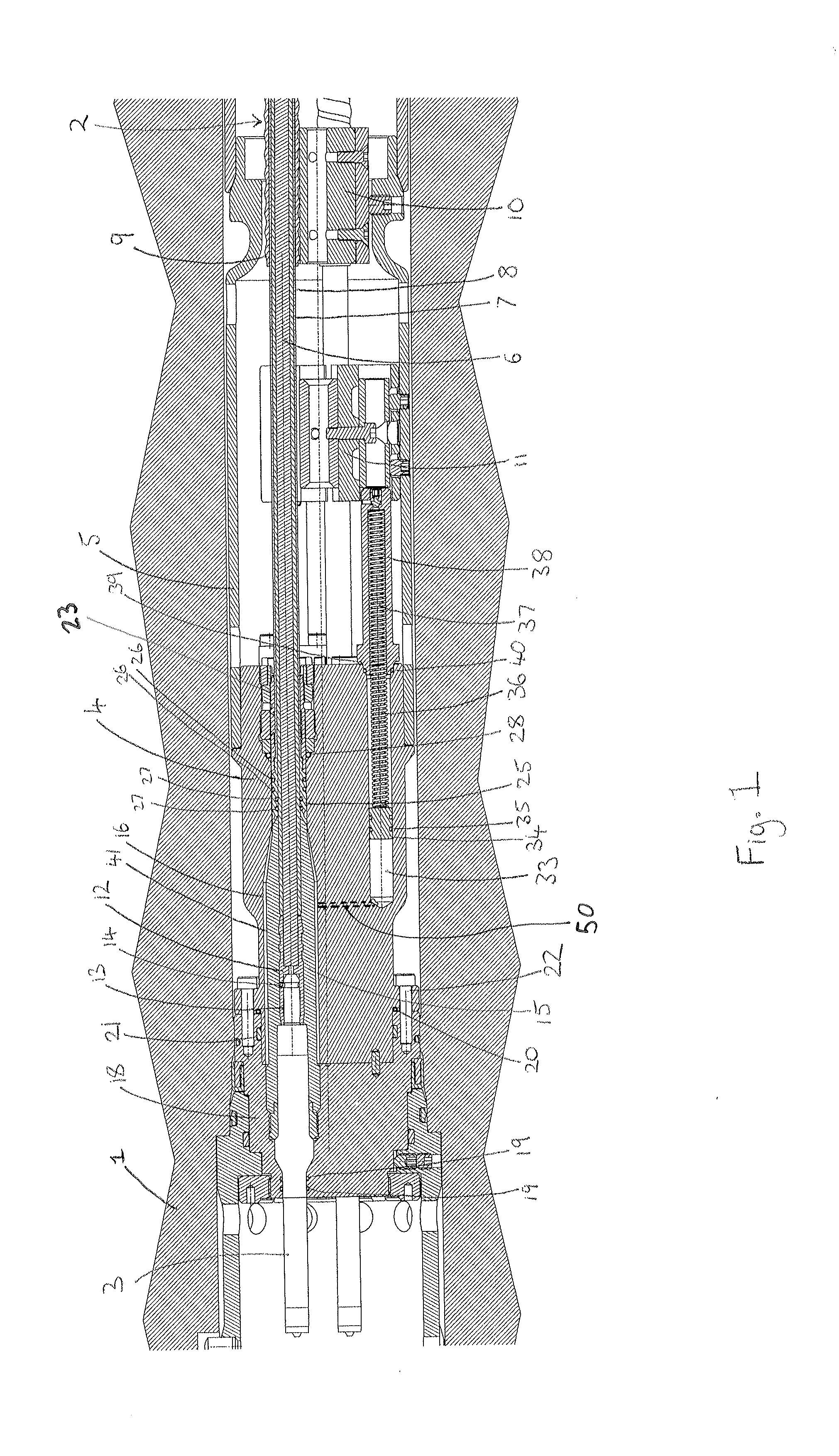
[0132]FIG. 1 shows one embodiment of a downhole cable termination assembly in a tubing hanger 1. A termination is made between a cable 2 and a pin 3 of a connector half that is arranged to be connected to another connector half to form a connector. The cable 2 extends downhole from the termination through a termination cover 4 and a tubing hanger receptacle gland housing 5 to electrical equipment (not shown) such as an electric submersible pump. There may be three cables within the termination apparatus. Each of the three cables is terminated to a pin 3 of the connector half. The arrangement shown in FIG. 1 has three cables, although the cross section is only through one of the cables and a corresponding compensation chamber (discussed below).

[0133]The cable 2 includes a conductive copper core 6 within an insulating polyether ether ketone (PEEK) sheath 7 that is within a lead sheath 8. The lead sheath is within a steel armor 9. Each layer of the cable 2 is concentric with the others...


PUM


Abstract

A downhole cable termination apparatus for terminating a cable that extends downhole into a downhole environment from a tubing hanger to electrical equipment is provided.

Description

[0001]This application claims the benefit of U.S. Provisional Patent Application No. 61 / 709,498, filed on Oct. 4, 2012, which is hereby incorporated by reference in its entirety. This application also claims the benefit of GB 1217788.7, filed on Oct. 4, 2012, which is hereby incorporated by reference in its entirety.BACKGROUND[0002]The present embodiments relate to a downhole cable termination apparatus.[0003]A subsea well may be provided with a tubing hanger for suspending production tubing that extends into a reservoir or a dummy reservoir. The tubing hanger may also house a connector that terminates a cable that extends downhole to supply power to electrical equipment such as an electric submersible pump located in the reservoir or dummy reservoir. Such connectors in the tubing hanger are subjected to hostile conditions such as extreme temperatures and pressures and aggressive chemicals, and thus, the connectors are to be designed to deal with these conditions.[0004]A known syste...

Claims


Application Information

Patent Timeline
Patent Type & Authority Patents(United States)
IPC IPC(8): H01R13/40H01R13/42H01R13/52
CPCH01R13/42H01R13/5205E21B17/023E21B17/028H01R13/5202H01R13/521H01R13/5216H01R13/523H01R13/533
Inventor BURROW, CHRISTOPHERSIMMONDS, MARK
Owner SIEMENS ENERGY GLOBAL GMBH & CO KG
Why Eureka
Try Eureka