Muffler for vehicle

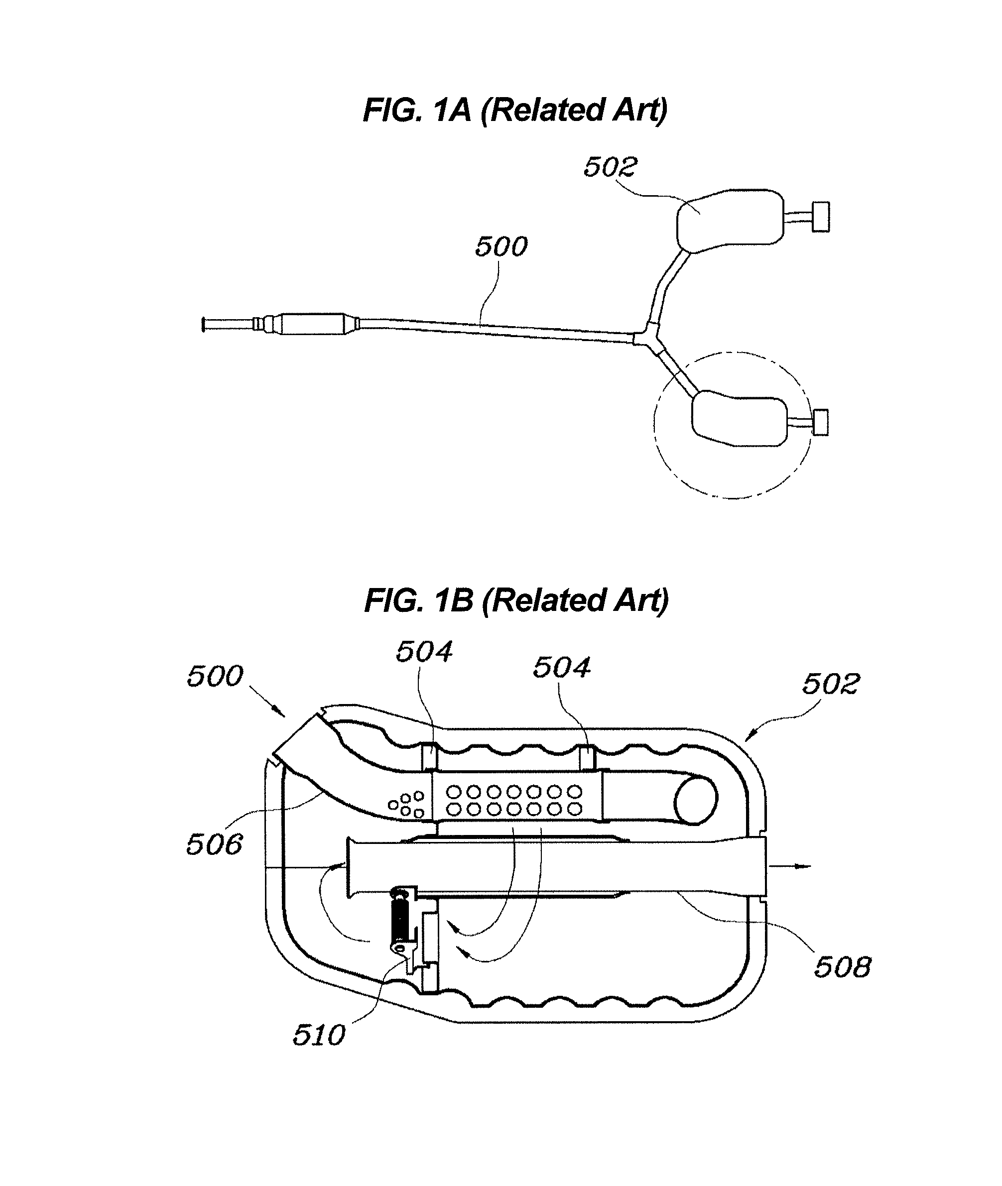
a technology for mufflers and vehicles, applied in the direction of machines/engines, gas passages, gas chambers, etc., can solve the problems of increasing back pressure, reducing engine power, and relatively expensive variable valves b>510/b>, so as to reduce back pressure, increase power, and reduce cost

Active Publication Date: 2015-12-15
HYUNDAI MOTOR CO LTD
View PDF18 Cites 1 Cited by
  • Summary
  • Abstract
  • Description
  • Claims
  • Application Information

AI Technical Summary

Benefits of technology

[0009]Various aspects of the present invention are directed to providing a muffler for a vehicle which reduces cost since an expensive muffler part is not used, and which reduces back pressure while increasing power in a low-medium speed range of an engine and realizes a sporty sound quality through the amplification of C4 and C6 components in the 200 Hz range of exhaust noise.
[0015]As set forth above, it is possible to reduce cost since an expensive muffler part is not used, reduce back pressure while increasing power in a low-medium speed range of an engine, and realize a sporty sound quality through the amplification of C4 and C6 components in the 200 Hz range of exhaust noise.

Problems solved by technology

However, the variable valve 510 is relatively expensive, and causes an increase in back pressure in the low-medium speed range, thereby reducing the power of the engine.

Method used


Image

  • Muffler for vehicle
  • Muffler for vehicle
  • Muffler for vehicle

Examples


Embodiment Construction

[0025]It should be understood that the appended drawings are not necessarily to scale, presenting a somewhat simplified representation of various features illustrative of the basic principles of the invention. The specific design features of the present invention as disclosed herein, including, for example, specific dimensions, orientations, locations, and shapes will be determined in part by the particular intended application and use environment.

[0026]In the figures, reference numbers refer to the same or equivalent parts of the present invention throughout the several figures of the drawing.

[0027]Reference will now be made in greater detail to an exemplary embodiment of the present invention, an example of which is illustrated in the accompanying drawings. Wherever possible, the same reference numerals will be used throughout the drawings and the description to refer to the same or like parts.

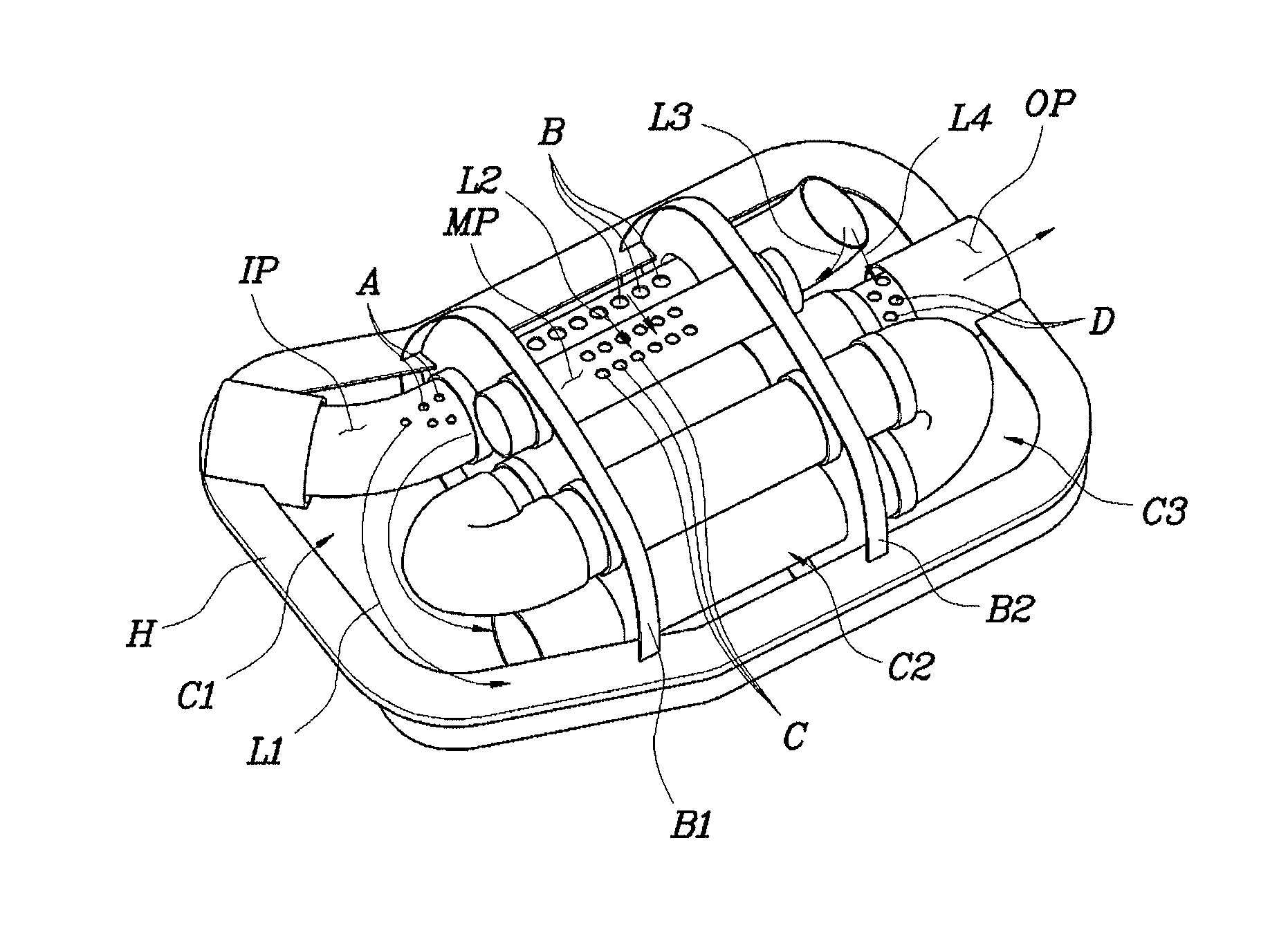
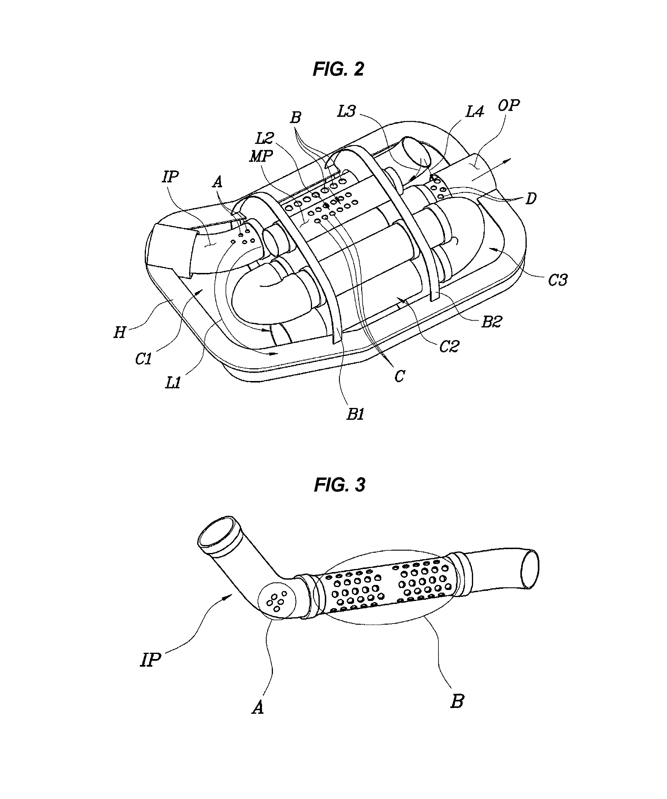
[0028]Referring to FIG. 2 to FIG. 4, a muffler for a vehicle according to an exemplary e...


PUM


Abstract

A muffler for a vehicle, may include a housing which defines a space therein, first and second baffles which partition the space inside the housing into first, second and third chambers, an inlet pipe which extends through the first baffle and the second baffle to be connected to the third chamber through the first chamber and the second chamber, an intermediate pipe which connects between the first and third chambers through the first baffle and the second baffle and has a plurality of holes in a portion thereof which may be placed in the second chamber, and an outlet pipe which sequentially extends through the first baffle and the second baffle from an first open end inside the first chamber, sequentially extends through the second baffle and the first baffle, sequentially extends through the first baffle and the second baffle, and then extends to the outside of the housing.

Description

CROSS-REFERENCE(S) TO RELATED APPLICATION[0001]The present application claims priority of Korean Patent Application Number 10-2013-0159545 filed on Dec. 19, 2013, the entire contents of which application is incorporated herein for all purposes by this reference.BACKGROUND OF THE INVENTION[0002]1. Field of the Invention[0003]The present invention relates to a muffler for a vehicle, and more particularly, to a technology for reducing back pressure, enhancing power, and obtaining a sporty sound quality in a low-medium speed range.[0004]2. Description of Related Art[0005]FIGS. 1A and 1B illustrate a conventional exhaust muffler structure for a vehicle. The muffler 502 having a specific volume is disposed on a rear part of an exhaust pipe 500 in order to reduce noise while discharging exhaust gas from an engine to the air.[0006]In addition, a plurality of chambers which are partitioned by a plurality of baffles 504 is provided inside a housing of the muffler 502. An inlet pipe 506 throug...

Claims


Application Information

Patent Timeline
Patent Type & Authority Patents(United States)
IPC IPC(8): F01N1/08
CPCF01N1/089F01N1/084F01N2470/02F01N2470/30F01N2490/06F01N1/02
Inventor HAN, HAK SONKONG, SEUNG TAE
Owner HYUNDAI MOTOR CO LTD
Why Eureka
Try Eureka