Shock absorber

a shock absorber and shock absorber technology, applied in the direction of shock absorbers, vibration dampers, springs/dampers, etc., can solve the problems of inability to variably control the damping force generated in high-frequency mode and low-frequency mode, and the conventional shock absorber has a limitation in improving ride comfort, so as to ensure steering stability

Active Publication Date: 2015-12-15
HL MANDO CORP
View PDF5 Cites 9 Cited by
  • Summary
  • Abstract
  • Description
  • Claims
  • Application Information

AI Technical Summary

Benefits of technology

[0011]The present invention has been made in an effort to solve the above problems and is directed to provide a shock absorber that implements a pressure-sensitive characteristic by using a pilot valve and controls a variable frequency characteristic, which is input from a road surface, through a lateral passage formed by an open of a guide member, thereby providing a round ride comfort having a damping feeling and ensuring a steering stability through a linear vehicle control.
[0013]In a high-frequency mode (a small-amplitude mode), the guide member may be opened such that the working fluid reduces a damping force while passing through the first pressure chamber and the third pressure chamber. In a low-frequency mode (a large-amplitude mode), the guide member may be prevented from being opened by increasing a pressure of the second pressure chamber formed between the second piston (lower piston) and the pilot valve through the groove formed in the outer periphery of the piston rod, and the working fluid generates a main damping force while sequentially passing through the first pressure chamber, the second pressure chamber, and the fourth pressure chamber.

Problems solved by technology

In the case of a high functional damper (HFD), a conventional shock absorber is effective in a high-speed degressive characteristic and an ultra-low-speed tuning, but cannot variably control a damping force generated in a high-frequency mode and a low-frequency mode.
Hence, the conventional shock absorber has a limitation in improving a ride comfort.

Method used


Image

  • Shock absorber
  • Shock absorber
  • Shock absorber

Examples


Embodiment Construction

[0020]Hereinafter, a shock absorber according to a preferred embodiment of the present invention will be described with reference to the accompanying drawings.

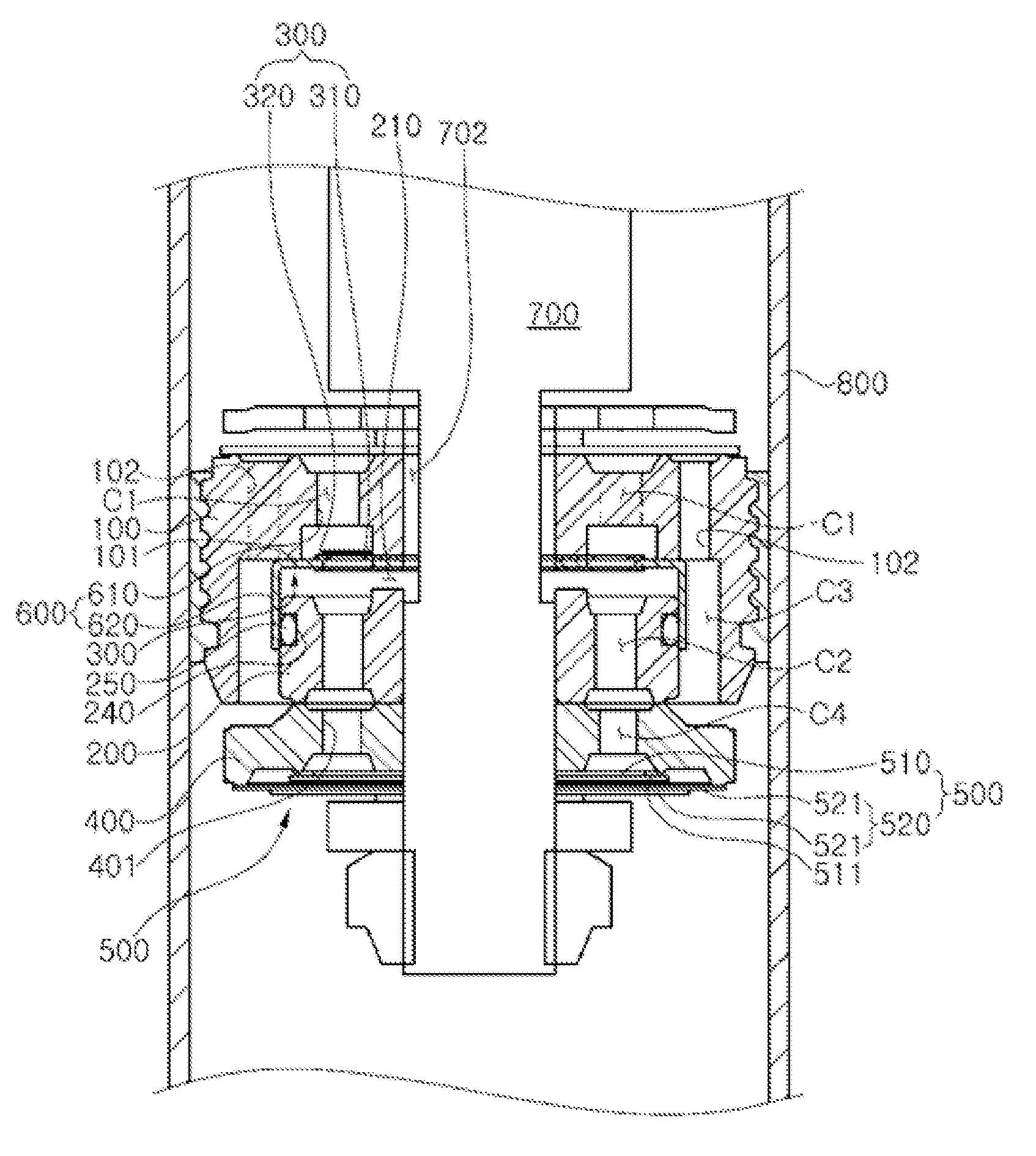
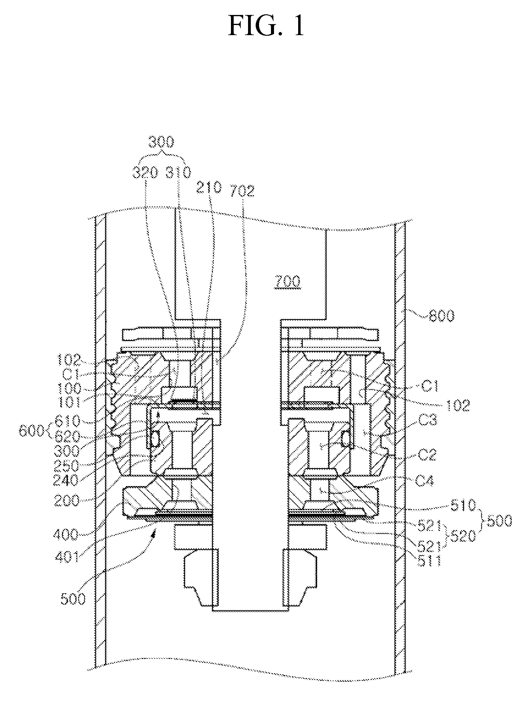
[0021]FIG. 1 is a cross-sectional conceptual diagram illustrating an overall configuration of a shock absorber according to an embodiment of the present invention, FIG. 2 is a cross-sectional conceptual diagram illustrating a flow of a working fluid in a high-frequency mode (a small-amplitude mode) during a rebound stroke in the shock absorber according to the embodiment of the present invention, and FIG. 3 is a cross-sectional conceptual diagram illustrating a flow of a working fluid in a low-frequency mode (a large-amplitude mode) during a rebound stroke in the shock absorber according to the embodiment of the present invention.

[0022]Referring to FIGS. 1 to 3, the shock absorber according to the preferred embodiment of the present invention includes a piston rod 700, a first piston 100, a pilot valve 300, a second piston (lo...


PUM


Abstract

In a high-frequency mode (a small-amplitude mode), a shock absorber opens a guide member to reduce a damping force. In a low-frequency mode (a large-amplitude mode), the shock absorber prevents the guide member from being opened by increasing a pressure of a second pressure chamber formed between a second piston (lower piston) and a pilot valve through a groove (passage) formed in an outer periphery of a piston rod. A main damping force is generated through the second pressure chamber and a disk valve assembly. Therefore, it is possible to provide a round ride comfort having a damping feeling and ensure a steering stability through a linear vehicle control.

Description

CROSS-REFERENCE(S) TO RELATED APPLICATION[0001]This application claims priority of Korean Patent Application No. 10-2013-0152412, filed on Dec. 9, 2013, in the Korean Intellectual Property Office, the contents of which are incorporated herein by reference in its entirety.BACKGROUND OF THE INVENTION[0002]1. Field of the Invention[0003]The present invention relates to a shock absorber, and more particularly, to a shock absorber which is capable of achieving a pressure-sensitive characteristic by using a pilot valve and controlling a variable frequency characteristic, which is input from a road surface, through a lateral passage formed by an open of a guide member.[0004]2. Description of the Related Art[0005]Generally, a shock absorber is designed to support a weight of a vehicle body and suppress and dampen a vibration transferred from a road surface to the vehicle body, contributing to improving a ride comfort and protecting loaded goods and various parts of a vehicle.[0006]Such a sh...

Claims


Application Information

Patent Timeline
Patent Type & Authority Patents(United States)
IPC IPC(8): F16F9/348F16F9/512
CPCF16F9/512F16F9/348F16F9/5126
Inventor KIM, TAE JU
Owner HL MANDO CORP
Why Eureka
Try Eureka