
Coated panel and method for manufacturing such panel

a technology of coating and coating layer, which is applied in the field of coating panel, can solve the problems of cumbersome surface structure of such coating layer, high cost of using such material sheet, and ticking sound, and achieve the effect of smoother and/or more economical performan

Active Publication Date: 2015-12-22
FLOORING IND LTD
View PDF78 Cites 4 Cited by
  • Summary
  • Abstract
  • Description
  • Claims
  • Application Information

AI Technical Summary

Benefits of technology

[0011]According to its various independent aspects, the present invention in particular aims at offering alternative coated panels of the above-mentioned type, which, according to various preferred embodiments thereof, can be performed smoother and / or more economical than the panels from the state of the art, and / or offer a remedy for one or more disadvantages of the panels and / or methods for manufacturing them of the state of the art.

Problems solved by technology

Moreover, the material and curing of a lacquer layer is expansive, and providing a structure in the surface of such lacquer layer is cumbersome.
The use of a material sheet as such is expensive, too.
A protective layer on the basis of thermohardening resin further also has the disadvantage that it may be cold to the touch and that it may result in ticking sounds when being walked on, when such panel is applied in a floor covering.
Moreover, for the curing thereof, relatively much energy is required, and realizing deep structures or relief is quite delicate.
These fibers may be applied for enabling the provision of thicker layers of synthetic material, however, also result in a certain loss of visibility of the motif, or loss of transparency of the layer concerned.
It is also noted that thermo-hardening resins, such as melamine resins, in general show the disadvantage that they do not or hardly adhere to prints which are performed by means of UV inks.
Moreover, according to some of the known techniques, the motif partially remains unprotected against, for example, wear or moisture penetration.
Also when no structure or relief is realized, such unevennesses may be inconvenient.
Moreover, substrates having relatively many unevennesses may be used, such as unsanded or hardly sanded MDF or HDF boards.
According to this possibility, possibly unsanded substrates can be used.
Such thickness leaves sufficient space for realizing mechanical coupling means.

Method used


Image

  • Coated panel and method for manufacturing such panel
  • Coated panel and method for manufacturing such panel
  • Coated panel and method for manufacturing such panel

Examples


Embodiment Construction

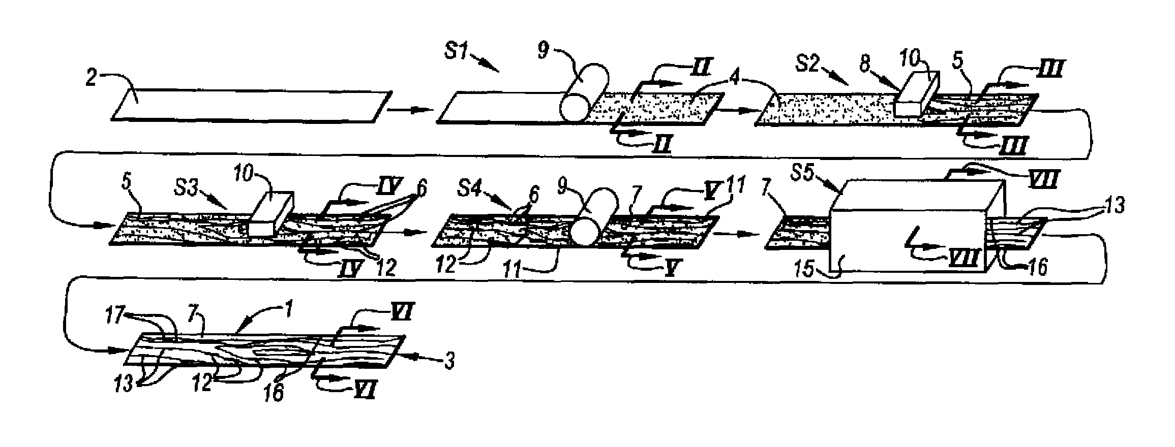
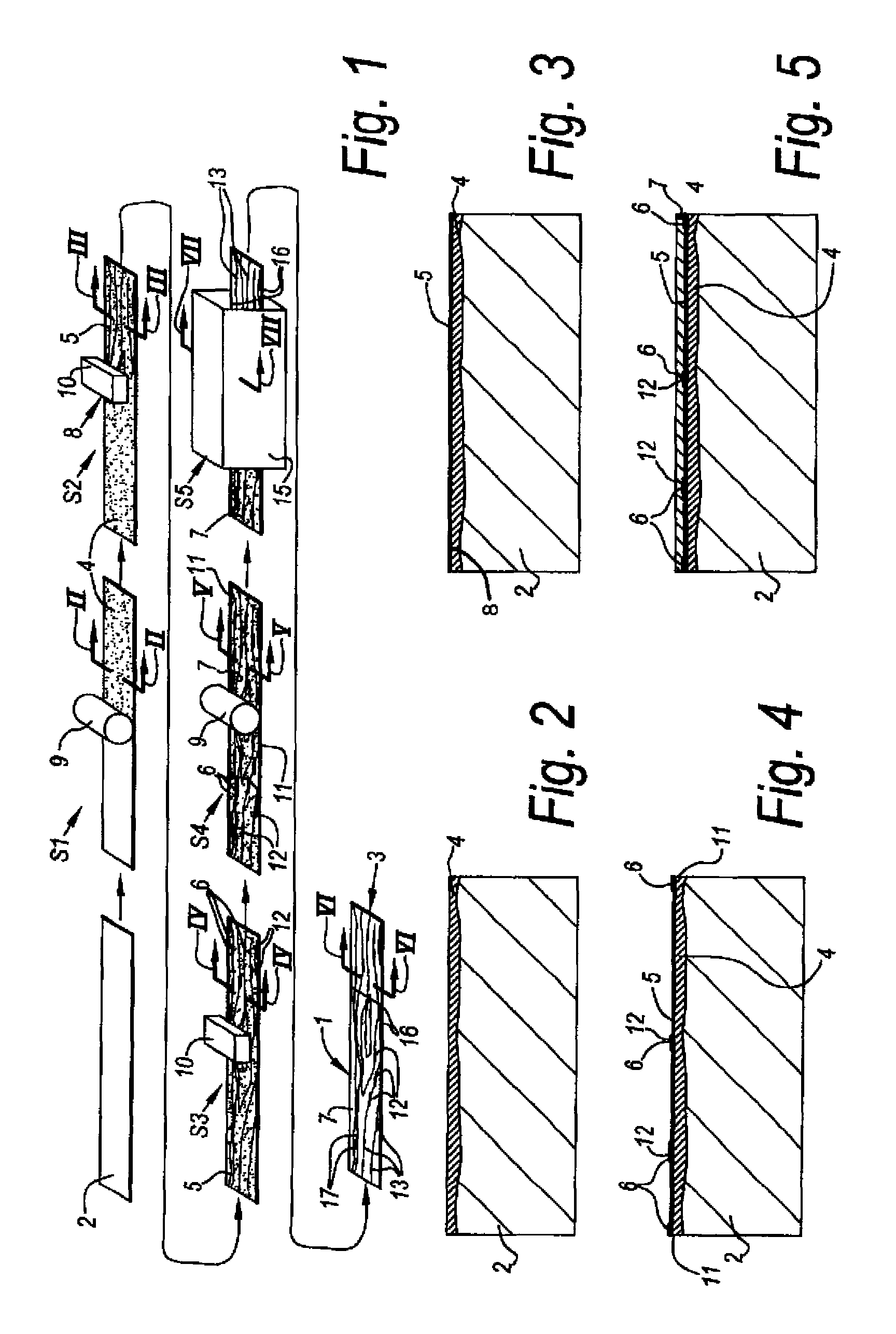
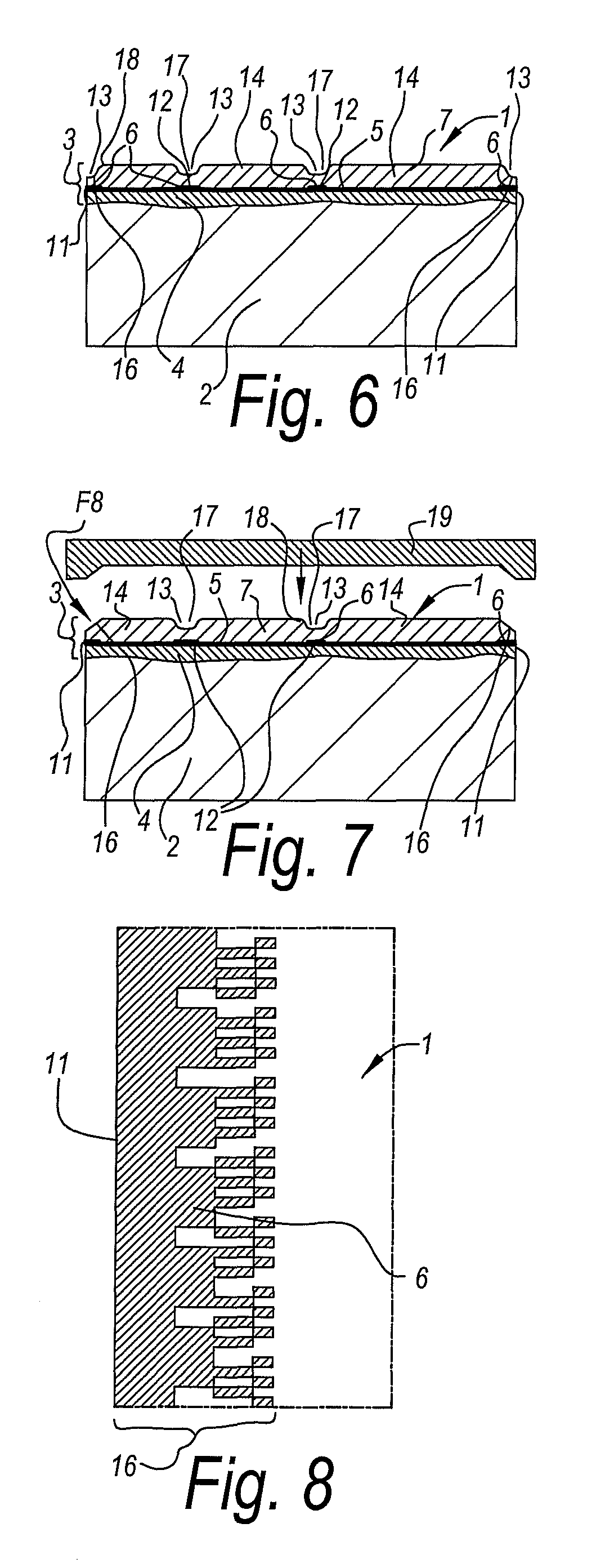
[0083]FIG. 1 schematically represents some steps S1-S5 in a method for manufacturing coated panels 1. The respective coated panels 1 are of the type comprising at least a substrate 2, for example, a MDF or HDF basic panel, and a top layer 3 provided on this substrate 2. In the example, the top layer 3 is composed of a plurality of material layers 4-7, amongst which a material layer 5, which shows a motif and which, during step S2, is provided in the form of a print 8 performed directly on the substrate 2.

[0084]In a previous step S1, one or more priming layers 4 are provided on the surface of the substrate 2 to be printed with the motif. These may have the purpose of providing a smooth subsurface and / or providing a uniform or quasi-uniform background color and / or an adhering undercoat for material layers 5-8 to be applied later, such as for the material layer 5 with the motif, or for the synthetic material layer 7. As mentioned in the introduction, all these functions possibly may be...


PUM

PropertyMeasurementUnit
thicknessaaaaaaaaaa
thicknessaaaaaaaaaa
thicknessaaaaaaaaaa

Abstract

A coated panel may include at least a substrate and a top layer with a printed motif. The top layer may be provided on the substrate. The top layer may also include a transparent or translucent synthetic material layer, which is provided above the printed motif. The top layer, and preferably at least the transparent or translucent synthetic material layer may include a foamable or foamed synthetic material.

Description

CROSS REFERENCE TO RELATED APPLICATIONS[0001]This US national phase application claims priority under 35 U.S.C. 119 (e) to U.S. provisional application No. 61 / 139,286 filed on Dec. 19, 2008, the content of which is incorporated herein in its entirety by reference.BACKGROUND OF THE INVENTION[0002]1. Field of the Invention[0003]This application relates to a coated panel and to a method for manufacturing such panel.[0004]More particularly, the invention relates to panels of the type comprising at least a substrate and a top layer with a motif, said top layer being provided on said substrate. Herein, this may relate, for example, to furniture panels, ceiling panels, floor panels or the like, which substantially consist of a MDF or HDF (Medium or High Density Fiberboard) basic panel or substrate and a top layer provided thereon. In particular, it relates to panels which comprise one or more material layers provided on the substrate, wherein at least one of these material layers shows a p...

Claims


Application Information

Patent Timeline
Patent Type & Authority Patents(United States)
IPC IPC(8): B44C5/04E04F15/02B44C1/22E04F13/08B44C1/20B44C1/10
CPCB44C5/04B44C1/10B44C1/20B44C1/22B44C5/0453E04F13/08E04F15/02E04F15/02033B44C5/043Y10T428/24884B44F9/02B44F9/04E04F13/0871E04F13/0866E04F15/107B05D5/00B05D3/12B41F17/00
Inventor SCHACHT, BENNYTACK, FILIP
Owner FLOORING IND LTD
Learn More