
Liquid-sealed-type anti-vibration device and method for manufacturing the same

a technology of anti-vibration device and liquid seal, which is applied in the direction of shock absorbers, manufacturing tools, machine supports, etc., can solve the problems of secondary failure, reduced passenger comfort, and rapid progress of rubber fatigue, so as to increase the volume change of the liquid chamber, improve the effect of vibration-damping performance and increase the volume of the liquid chamber

Active Publication Date: 2015-12-29
PROSPIRA CORP
View PDF22 Cites 4 Cited by
  • Summary
  • Abstract
  • Description
  • Claims
  • Application Information

AI Technical Summary

Benefits of technology

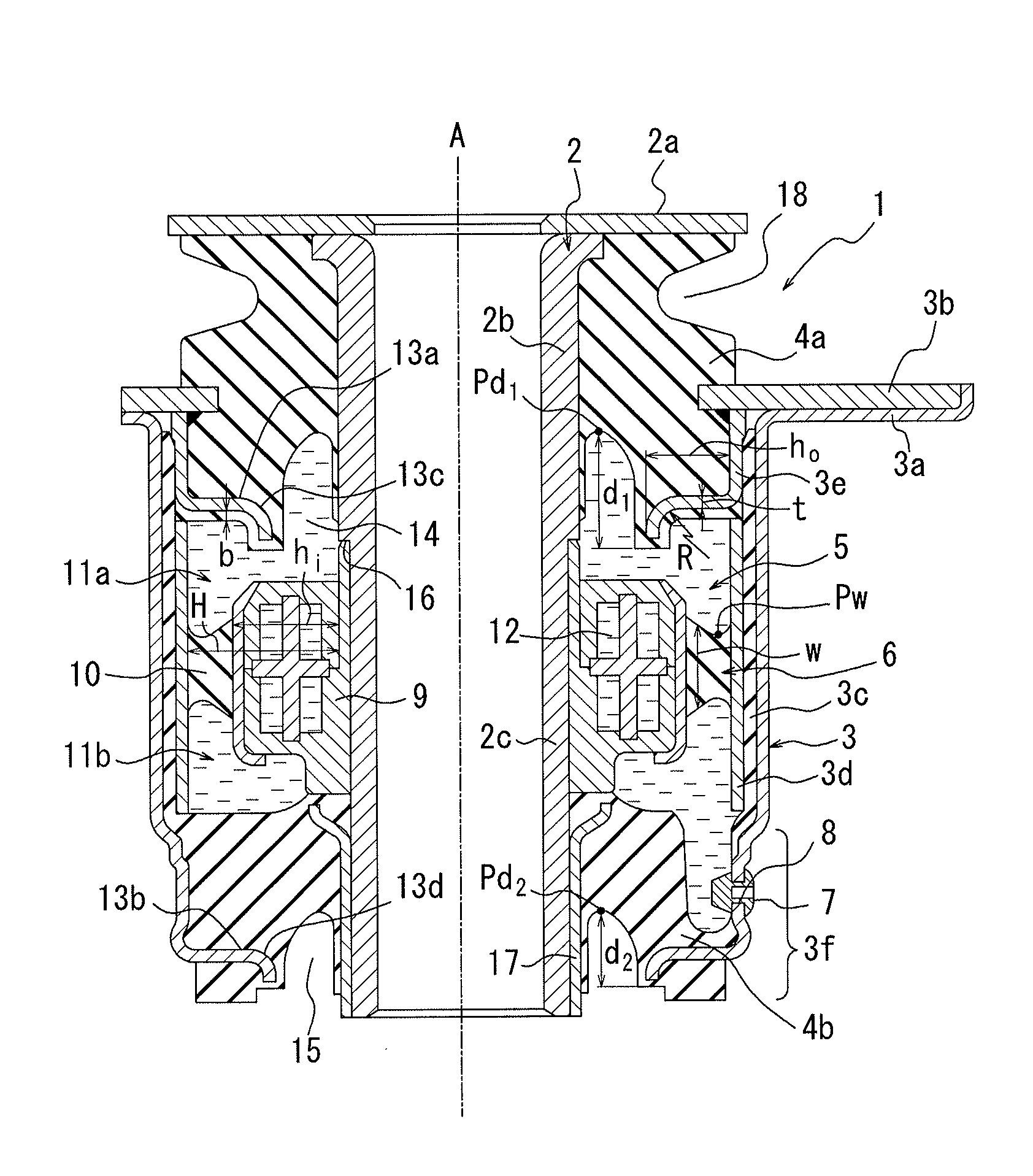
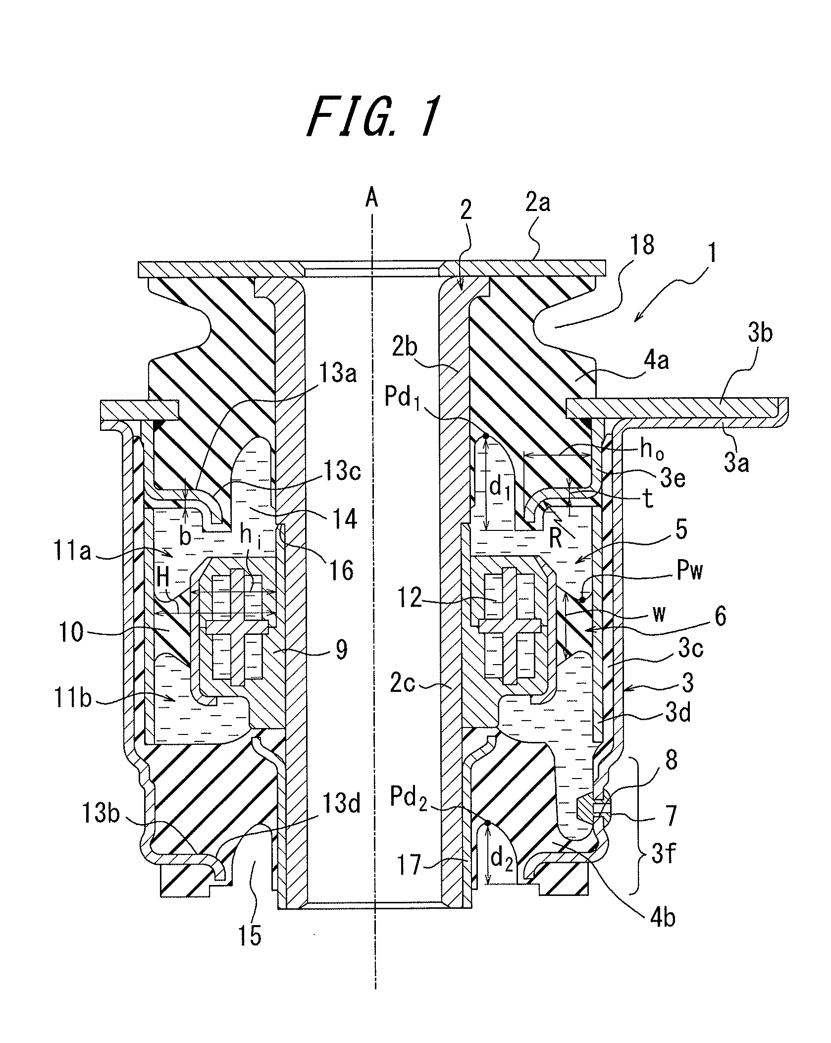
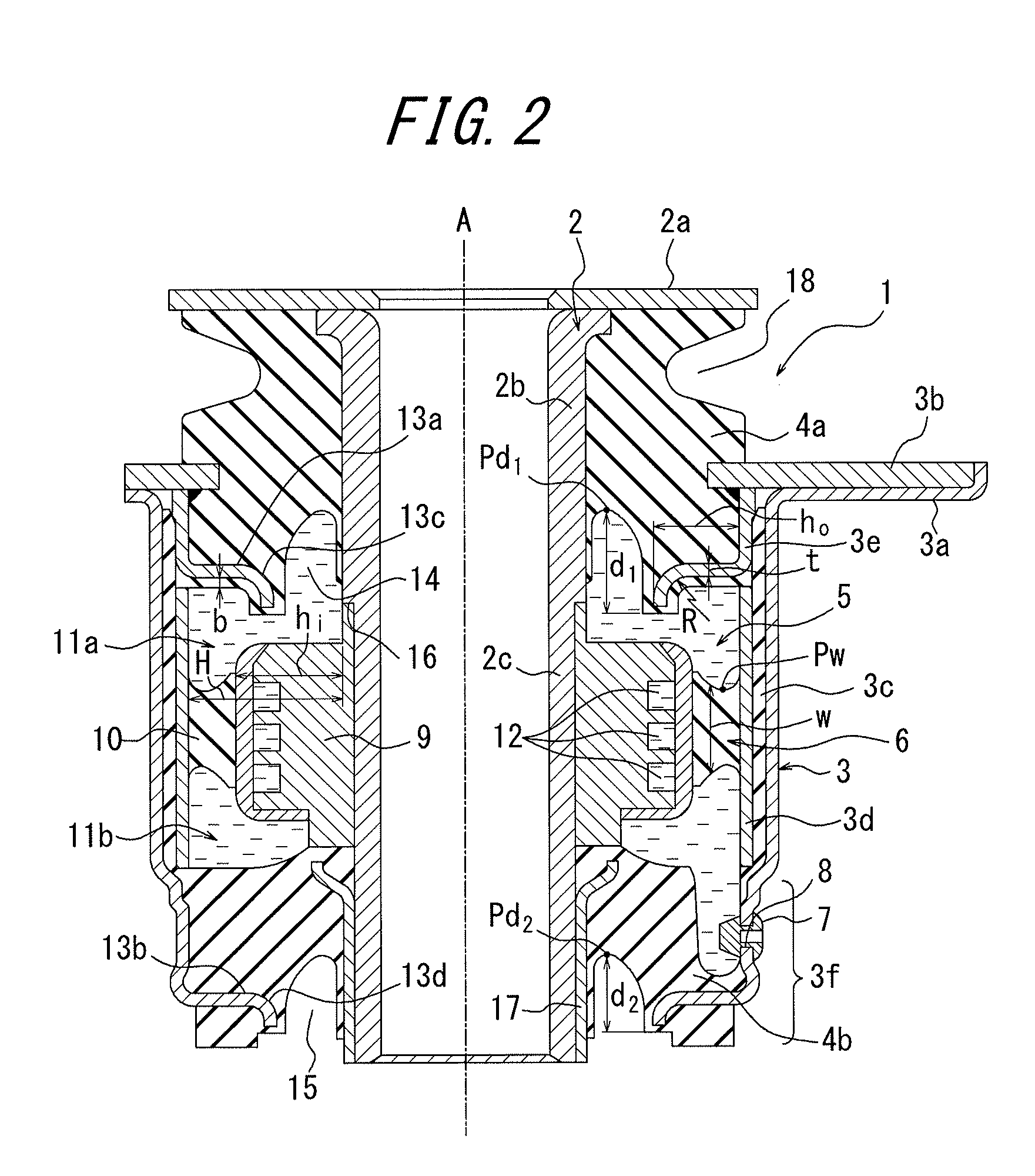
[0040]In the liquid-sealed-type anti-vibration device of the present invention, the outer circumferential surface of the inner-tube member is provided with the inner-tube rigid protrusion, and the inner circumferential surface of the outer-tube member is provided with the first outer-tube rigid protrusion and the second outer-tube rigid protrusion. Accordingly, upon a vibration input, the inner-tube rigid protrusion and the outer-tube rigid protrusions move closer to or away from each other, thereby increasing the volume change of the liquid chambers. Therefore, similarly to the liquid-sealed-type anti-vibration device disclosed in Patent Document 1, it is possible to achieve excellent vibration-damping performance.
[0041]In the conventional liquid-sealed-type anti-vibration device disclosed in Patent Document 1, the inner circumferential surface of the outer-tube member is provided with the ring-shaped first outer-tube rigid protrusion and second outer-tube rigid protrusion, the inner circumferential surfaces of these outer-tube rigid protrusions are fixed to the rubber bodies, and the substantial volumes of the rubber bodies are not sufficiently large. Accordingly, in the conventional device, there is a drawback in that as impact vibration is input, the rubber bodies are subjected to extreme shear deformation, and thereby the rubber fatigue quickly progresses as discussed above. According to the liquid-sealed-type anti-vibration device of the present invention, since each of the outer-tube rigid protrusions has a shape of an inward flange such that its axial width is sufficiently small with respect to its radial height (protruding length), the volumes of the rubber bodies may be sufficiently large, and the shear deformation of the rubber bodies in response to a vibration input may be effectively dispersed, thereby suppressing the progression of the rubber fatigue.
[0042]In addition, since the depths of the ring-shaped cavities are configured such that the cavities extend beyond the outer-tube protrusions, upon relative displacement of the inner-tube member and outer-tube member in the axial direction, the rubber portions around the cavities sufficiently bend, thereby mitigating the concentration of stress at the fixing surfaces between the rubber bodies and outer-tube rigid protrusions. Accordingly, it is possible to reduce the separation at the fixing surfaces.
[0043]On the other hand, as in the conventional liquid-sealed-type anti-vibration device, if the depths of the cavities are configured such that the cavities do not extend beyond the outer-tube rigid protrusions, the rubber portions near the cavities do not sufficiently bend, and thus it is not possible to mitigate the concentration of stress at the fixing surfaces and to reduce the separation at the fixing surfaces.
[0044]According to the present invention, a liquid-sealed-type anti-vibration device which has excellent damping performance, effectively reduces separation due to progression of fatigue of the rubber bodies and concentration of stress at the fixing surfaces between the rubber bodies and outer-tube rigid protrusions, and has significantly improved durability, may be provided.
[0045]According to the liquid-sealed-type anti-vibration device of the present invention, since at least one of the first outer-tube rigid protrusion and the second outer-tube rigid protrusion is located on the side of the liquid chambers, a large portion of rubber resides on the opposite side of the liquid chambers with respect to the outer-tube rigid protrusion, and thereby it is possible to more effectively disperse the shear deformation of the rubber bodies upon a vibration input.

Problems solved by technology

Accordingly, there is a drawback that, when a large impact force is input by the member on the vibration-generating side such that the relative displacement of the inner-tube member 102 and the outer-tube member 103 in the axial direction is particularly large for example, the rubber bodies 104a, 104b are subjected to extreme shear deformation, and thereby the rubber fatigue quickly progresses.
If the rubber bodies 104a, 104b experience fatigue breakage and the like, the vibration at the unsprung side of the vehicle is directly transmitted to the cabin, thereby decreasing the passenger comfort, and in addition, the vibration adversely affects other devices in the vehicle, thereby inducing secondary failures and potentially causing a severe vehicle malfunction or accident.
Accordingly, in such a liquid-sealed-type anti-vibration device, excellent damping performance as well as excellent durability are required, however, the technology disclosed in Patent Document 1 is not sufficient.
In a case where improved damping performance at a certain frequency range is desired, it is sometimes preferable to use low viscous liquid, however, in such a case, sufficient damping performance cannot be achieved by the aforementioned damping plate.
Accordingly, the technology disclosed in Patent Document 2 is not highly adaptable to the vibration at frequencies outside of the certain frequency range.
However, in these technologies, since the protruding portion does not move with the upward and downward displacement of an inner-tube member, it is not possible to achieve large volume change of liquid chambers by the upward and downward displacement of the protruding portion.

Method used


Image

  • Liquid-sealed-type anti-vibration device and method for manufacturing the same
  • Liquid-sealed-type anti-vibration device and method for manufacturing the same
  • Liquid-sealed-type anti-vibration device and method for manufacturing the same

Examples


Embodiment Construction

[0108]The present invention will be described in detail below with reference to the accompanying drawings. In the embodiment shown in FIG. 1, a liquid-sealed anti-vibration device 1 comprises an inner-tube member 2 to be mounted to a member on either one of the vibration-generating side and the vibration-transmitted side; an outer-tube member 3 located coaxially with and outside of the inner-tube member 2, to be connected to the member on the other one of the vibration-generating side and the vibration-transmitted side; a first rubber body 4a for connecting one end of the outer-tube member 3 with the outer circumferential surface of the inner-tube member 2 in a liquid-tight manner; a second rubber body 4b for connecting the other end of the outer-tube member 3 with the outer circumferential surface of the inner-tube member 2 in a liquid-tight manner; and a fluid chamber 5 configured in such a way that the space defined by the first rubber body 4a, the second rubber body 4b, the inne...


PUM

PropertyMeasurementUnit
widthaaaaaaaaaa
widthaaaaaaaaaa
curvature radiusaaaaaaaaaa

Abstract

The present invention provides a liquid-sealed-type anti-vibration device that achieves damping performance as well as durability, the device comprising: an inner-tube member; an outer-tube member; first and second rubber bodies; and a fluid chamber, wherein a partition member, which is provided on the inner-tube member and has an inner-tube rigid protrusion and a rubber partition, is provided with a limiting passage, the outer-tube member has first and second outer-tube rigid protrusions having a shape of an inward flange, at least one of the first and second outer-tube rigid protrusions is disposed on the side of liquid chambers, each of the first rubber body and the second rubber body is provided with a ring-shaped cavity extending inside the respective rubber body along the outer circumferential surface of the inner-tube member, the depth of the cavities being configured such that the cavities extend beyond the first outer-tube rigid protrusion or the second outer-tube rigid protrusion, and at least one of the cavities faces one of the liquid chambers.

Description

CROSS REFERENCE TO RELATED APPLICATIONS[0001]This application is a National Stage of International Application No. PCT / JP2011 / 001270 filed Mar. 3, 2011, claiming priority based on Japanese Patent Application Nos. 2010-064951 filed Mar. 19, 2010, 2010-100024 filed Apr. 24, 2010 and 2010-107596 filed May 7, 2010, the contents of all of which are incorporated herein by reference in their entirety.TECHNICAL FIELD[0002]The present invention relates to a liquid-sealed-type anti-vibration device suitable for use as a cabin mount, an engine mount and the like of a vehicle and a method for manufacturing the same. The present invention particularly proposes a technology for a liquid-sealed-type anti-vibration device capable of achieving at a high level excellent damping performance against a vibration input as well as durability of rubber.BACKGROUND ART[0003]A conventional anti-vibration device for preventing the vibration generated at the unsprung side of the vehicle from being transmitted t...

Claims


Application Information

Patent Timeline
Patent Type & Authority Patents(United States)
IPC IPC(8): F16F13/00F16F13/16F16F13/14
CPCF16F13/16F16F13/1481Y10T29/49826
Inventor SAITO, AKIHIROSOMEYA, KATSUMI
Owner PROSPIRA CORP
Learn More