Mud high-pressure filtering and compressed dewatering testing cavity and device

A technology for testing chambers and mud, applied in the field of mud high-pressure filtration compression dehydration test chambers and test devices, can solve the problems of narrow applicability of conclusions, single dehydration performance test indicators, poor reliability, etc. The effect of liquid separation equipment selection

Pending Publication Date: 2019-02-22
INST OF ROCK AND SOIL MECHANICS - CHINESE ACAD OF SCI +1
View PDF0 Cites 1 Cited by
  • Summary
  • Abstract
  • Description
  • Claims
  • Application Information

AI Technical Summary

Problems solved by technology

[0004] The invention provides a mud piston filter compression dehydration test chamber, which solves the technical problems in the prior art that the preliminary dehydration performance test index of the mud is single at the laboratory scale, the conclusion is narrow in applicability, and poor in reliability.

Method used


Image

  • Mud high-pressure filtering and compressed dewatering testing cavity and device
  • Mud high-pressure filtering and compressed dewatering testing cavity and device

Examples


Embodiment 1

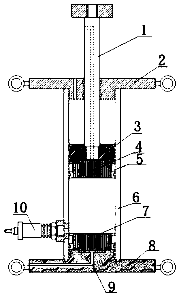
[0041] see figure 1 , a mud piston filtration compression dehydration test chamber, including: push rod 1, top cover 2, cylinder 6, piston 3, lower end permeable plate 7, base 9 and first water pressure transmitter 10.

[0042] The force applying push rod 1 is embedded in the through hole opened on the top cover 2, and can move axially, so that the dehydration pressure can be applied under the action of the externally connected power element; generally speaking, the power element can adopt hydraulic pressure. system so that changes in applied pressure can be acquired in real time.

[0043] The top cover 2 is detachably sealed on the top port of the cylinder 6 to form a cylindrical cavity with an openable upper end for pressing and dehydration operation.

[0044] The piston 3 abuts against the inner cavity wall of the cylinder 6 and is fixedly connected with the first end of the pushing rod 1, and can move along the cylinder under the driving of the pushing rod 1. The wall of...

Embodiment 2

[0052] see figure 1 , on the basis of Example 1, the structure of double-sided drainage is set to facilitate the research of this kind of solid-liquid separation process operation and equipment.

[0053] The cavity also includes: an upper permeable plate 4; the upper permeable plate 4 abuts against the lower end surface of the piston 3, thereby forming a solid-liquid separation structure similar to the lower permeable plate 7, and realizing the separation of the upper end and the lower end. Composite Structure.

[0054]Specifically, an upper liquid discharge channel is opened in the pushing rod 1 and communicates with the liquid outlet of the upper permeable plate 4 .

[0055] In order to facilitate the collection of liquid discharge, a first liquid collection tank is provided on the lower end surface of the piston 4, and the bottom of the first liquid collection tank communicates with the upper liquid discharge channel; above the first sump.

[0056] Further, the groove sh...

Embodiment 3

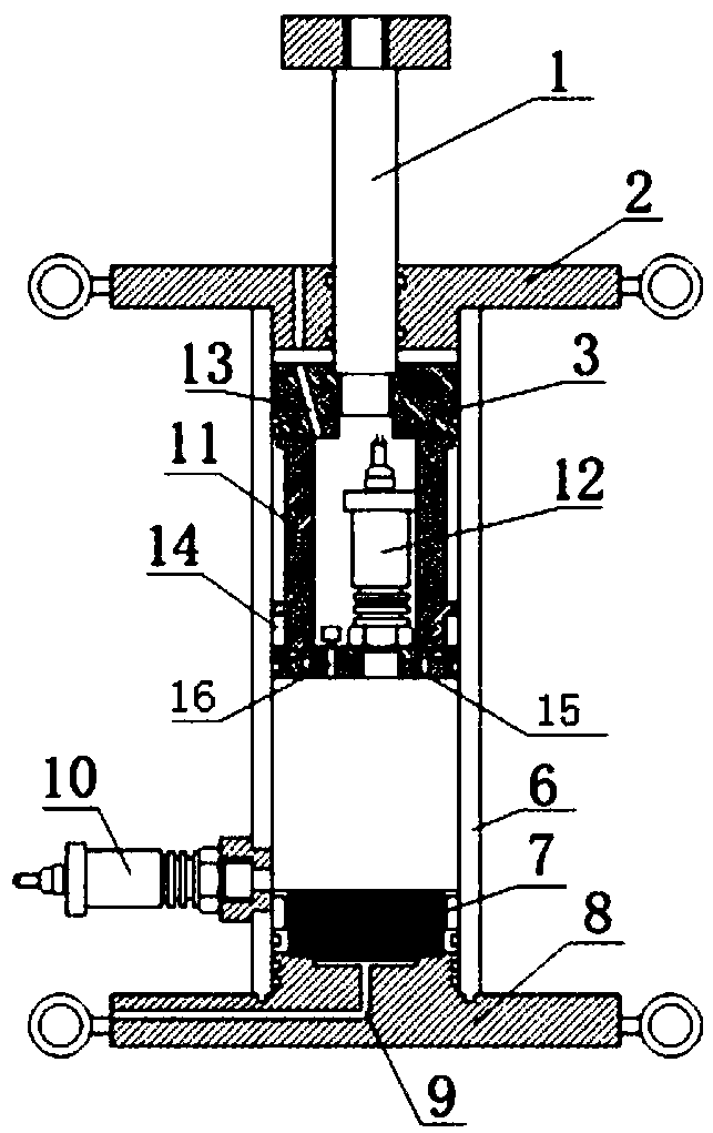
[0064] see figure 2 , On the basis of Embodiment 1, a single-ended drainage measurement structure is adopted.


PUM


Abstract

The invention belongs to the technical field of environmental geotechnics and discloses a mud high-pressure filtering and compressed dewatering testing cavity. The mud high-pressure filtering and compressed dewatering testing cavity comprises a force application pushrod, a top cover, a cylinder barrel, a piston, a lower porous plate, a base and a first water pressure transmitter, wherein the forceapplication pushrod is embedded inside a through hole formed in the top cover and can move axially; the top cover is detachably arranged on the top opening of the cylinder barrel in a sealed mode; the piston abuts against the inner wall of the cylinder barrel and is fixedly connected with the first end of the force application pushrod and driven by the force application push rod to move axially along the inner wall of the cylinder barrel; the base is arranged on the bottom opening in a sealed mode on the cylinder barrel; the lower porous plate is arranged in the lower portion of the inner cavity of the cylinder barrel and abuts against the base; the sensing end of the first water pressure transmitter is fixed inside the inner cavity of the cylinder barrel; the base is provided with a lower drainage channel and communicated with the liquid outlet of the lower porous plate. The mud high-pressure filtering and compressed dewatering testing cavity can in real time convert data of transmission pressure application change, liquid drainage and liquid pressure, thereby increasing diversity of testing data.

Description

technical field [0001] The invention relates to the technical field of environmental geotechnical engineering, in particular to a mud high-pressure filtration compression dehydration test cavity and a test device. Background technique [0002] In the treatment and disposal of municipal sludge, reducing the water content of sludge is an effective means to achieve volume reduction, so it is often necessary to separate solid-liquid from sludge. According to the dehydration form, the existing solid-liquid separation equipment can be roughly divided into belt filter press, plate and frame extrusion and centrifugal separation. difference. In order to select the appropriate dehydration equipment, operation process, dehydration test is usually required. [0003] Preliminary dewatering performance testing of mud at a laboratory scale is a common choice. Mainly include: capillary water absorption time test, specific resistance test, zeta potential test and other methods, these meth...

Claims


Application Information

Patent Timeline
IPC IPC(8): G01N33/24C02F11/121
CPCG01N33/24C02F11/121
Inventor 谭洵薛强陈亿军万勇王平张少华
Owner INST OF ROCK AND SOIL MECHANICS - CHINESE ACAD OF SCI
Why Eureka
Try Eureka