Electrical mitigation of DML nonlinearity for high-speed optical interconnection

a technology of nonlinearity and high-speed optical interconnection, which is applied in the direction of electrical equipment, electromagnetic transmission, transmission, etc., can solve the problems that dmls can experience bandwidth and nonlinearity limitations at some data rates

Active Publication Date: 2016-01-05
GOOGLE LLC
View PDF7 Cites 18 Cited by
  • Summary
  • Abstract
  • Description
  • Claims
  • Application Information

AI Technical Summary

Problems solved by technology

However, the DMLs can experience bandwidth and nonlinearity limitations at some data rates.

Method used


Image

  • Electrical mitigation of DML nonlinearity for high-speed optical interconnection
  • Electrical mitigation of DML nonlinearity for high-speed optical interconnection
  • Electrical mitigation of DML nonlinearity for high-speed optical interconnection

Examples


Embodiment Construction

[0009]The various concepts introduced above and discussed in greater detail below may be implemented in any of numerous ways, as the described concepts are not limited to any particular manner of implementation. Examples of specific implementations and applications are provided primarily for illustrative purposes.

[0010]In some implementations, the output of a directly modulated laser (DML) includes nonlinearities with respect to the input signal driving the DML. When the DML is transmitting an amplitude modulated signal, the nonlinearities can induce noise into the signal, which makes it difficult for a receiving node to correctly decode the received signal. The system and methods described herein pre-correct the error caused by the nonlinearities of the DML by filtering (or pre-correcting) the data signal that drives the DML.

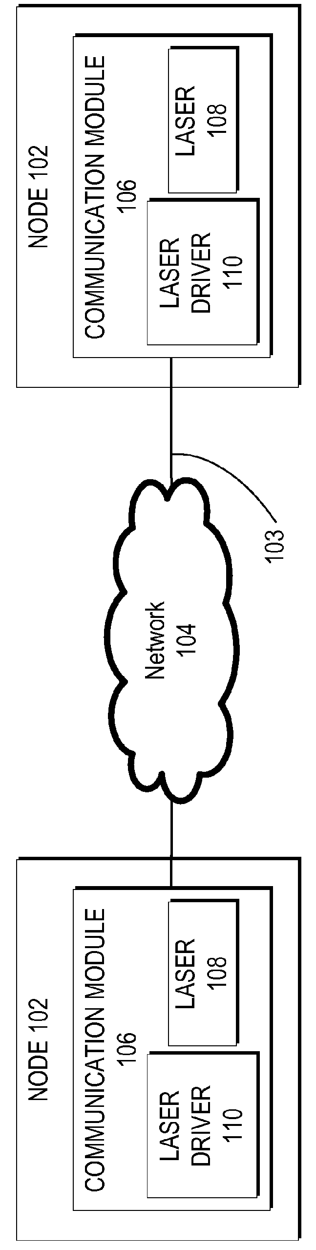
[0011]FIG. 1 illustrates an example system 100. The system 100 includes nodes 102 connected with one another through a network 104. Each of the nodes 102 inclu...


PUM


Abstract

In some implementations, the output of a directly modulated laser (DML) includes nonlinearities with respect to the input signal driving the DML. When the DML is transmitting an amplitude modulated signal, the nonlinearities can induce noise into the signal, which makes it difficult for a receiving node to correctly decode the received signal. The system and methods described herein pre-correct the error caused by the nonlinearities of the DML by filtering (or pre-correcting) the data signal that drives the DML.

Description

BACKGROUND OF THE DISCLOSURE[0001]Nodes within datacenters can communicate through fiber optic networks. In some implementations, data is transmitted over the fiber optic networks with directly modulated lasers (DML). DMLs can be low cost, have a low power consumption, and have a small footprint. However, the DMLs can experience bandwidth and nonlinearity limitations at some data rates.SUMMARY OF THE DISCLOSURE[0002]According to one aspect of the disclosure a method for pre-correcting the distortion of a directly modulated laser includes providing a plurality of pre-equalization functions. Each of the plurality of pre-equalization functions includes a transfer function. Each of the transfer functions is configured to filter a different amplitude range of an input signal. The method also includes receiving a signal and decomposing the signal into a plurality of sub-signals. Each of the plurality of sub-signals is filtered with one of the plurality of pre-equalization functions. The f...

Claims


Application Information

Patent Timeline
Patent Type & Authority Patents(United States)
IPC IPC(8): H04B10/54H04B10/50H04B10/524
CPCH04B10/504H04B10/58
Inventor ZHOU, XIANGMAO, ERJI
Owner GOOGLE LLC
Why Eureka
Try Eureka