All-weather enclosure for flat panel displays

an enclosure and flat panel technology, applied in the field of allweather enclosures for flat panel displays, can solve the problems of compromising the weatherproof nature of the enclosure, preventing the use of the standard ceiling and wall mounting system, and simple enclosures lacking structural rigidity to adequately protect the flat panel display. , to achieve the effect of increasing the structural rigidity of the containing elemen

Active Publication Date: 2016-01-12
PROTECTIVE ENCLOSURES CO LLC
View PDF8 Cites 10 Cited by
  • Summary
  • Abstract
  • Description
  • Claims
  • Application Information

AI Technical Summary

Benefits of technology

[0010]The containing element is constructed of polystyrene, high-density polyethylene, or some similar substance and is generally in the form of a recessed shallow rectangular prism reinforced with a network of molded indentations formed in its outer surface. These molded indentations serve to increase the structural rigidity of the containing element. While these indentations are regularly spaced across the outer surface of the containing element, they are absent in the center portion of the back wall of the containing element to allow for drilled or molded holes used to secure the flat panel display and protective enclosure to a standard mounting device. Also, the lower wall of the containing element has one or more mating slots, molded indentations, or similar tang receiving means that interoperate with the locking tangs present on the compression key latches, or similar locking means, attached to the viewing element. The bottom wall of the containing element is perforated to allow access for power and signal cables. Similarly, the left and right sides of the containing element are perforated by one or more air vents.

Problems solved by technology

Unfortunately, most have the same shortcomings, to wit: 1) They are made primarily of metal, metal and plastic, or even wood; and, 2) They are heavy, thus requiring that that they be mounted directly to a wall or other structure capable of bearing their weight and thus prohibiting their use with the standard ceiling and wall mounting systems commonly used to mount flat-panel displays today; and, 3) Because of the weight and complexity they are expensive.
While such enclosures may be suitable for small flat-panel displays, when “scaled” to enclose the larger flat-panel displays now commonly available, such simple enclosures do not possess sufficient structural rigidity to adequately protect the flat-panel display.
The principal difficulty arises because the use of readily available prefabricated light plastic material results in a relatively flimsy enclosure that deforms and warps easily, thus compromising the weatherproof nature of the enclosure.
Moreover, because one large side of the enclosure must be constructed of some transparent material, such as polycarbonate, any warping of the enclosure also affects the optical clarity of the polycarbonate, thus distorting the image generated by the enclosed display.
By using thicker, heavier plastic, such devices can be made with increased structural rigidity, but consequently such devices are heavier and more expensive to manufacture and mount.
While certainly rigid, these devices are by no means lightweight.
While the inventions disclosed by U.S. Pat. No. 8,081,267 and U.S. Pat. No. 8,102,483 do not permanently seal the device within, they offer no easy means of ingress for maintenance or adjustment of the enclosed flat-panel display.
These sealed devices are thus unsuitable for ordinary consumer and home use.
Unfortunately, this device is constructed of a multitude of parts and is quite heavy thus making it impractical if not mounted directly to a wall.
Finally, all of the above inventions contain numerous constituent parts and are costly to manufacture.

Method used


Image

  • All-weather enclosure for flat panel displays
  • All-weather enclosure for flat panel displays
  • All-weather enclosure for flat panel displays

Examples


Embodiment Construction

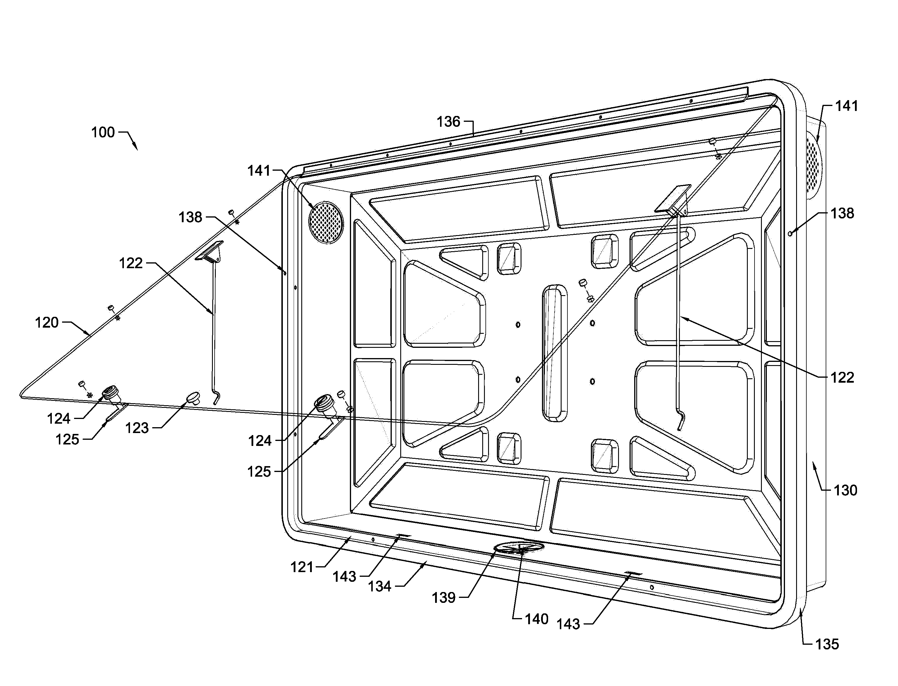
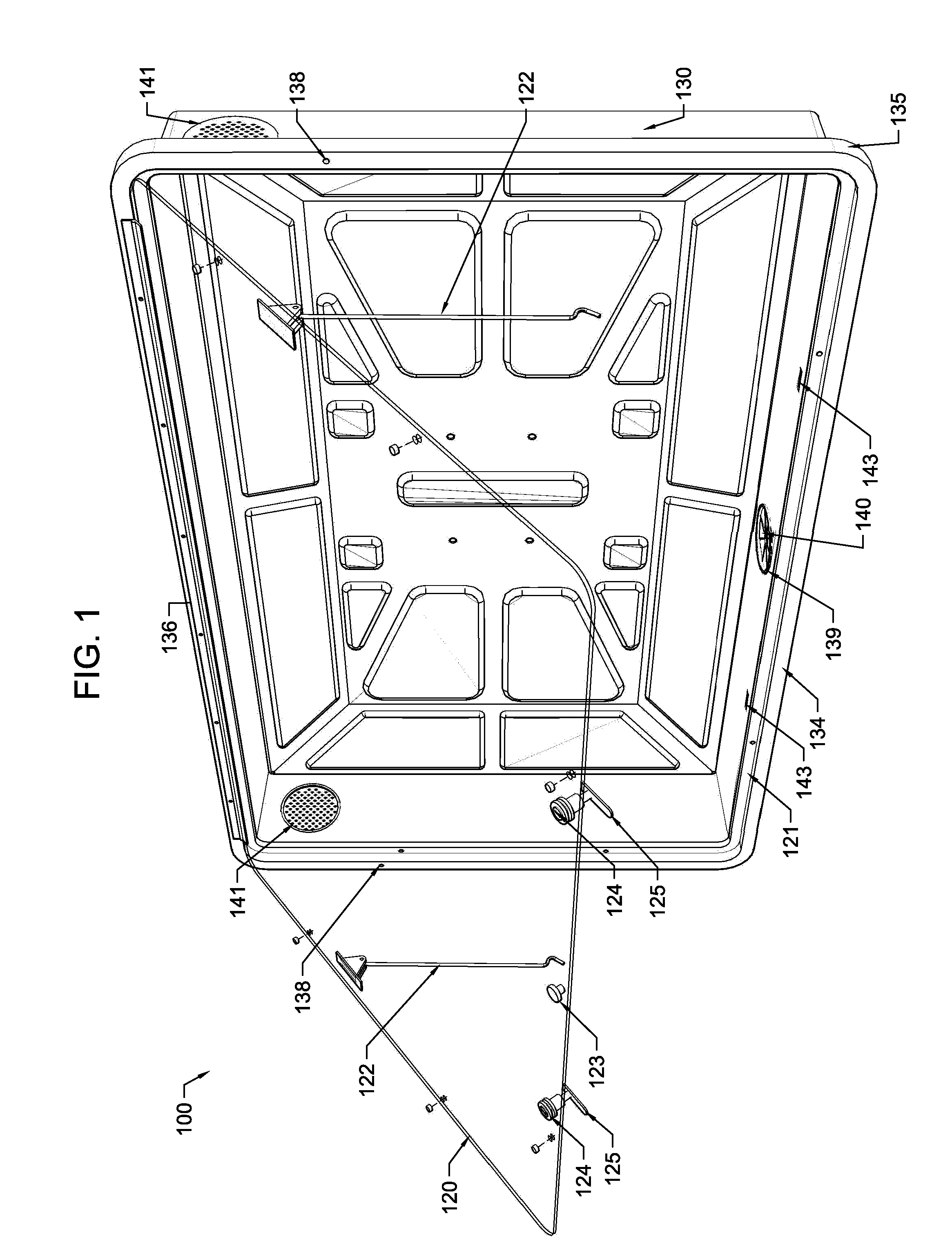
[0017]Referring now to FIGS. 1 and 2, a protective enclosure 100 used to enclose and protect a flat panel display, or equivalent, comprised of a front, planar viewing element 120 and a rear, recessed containing element 130 is disclosed.

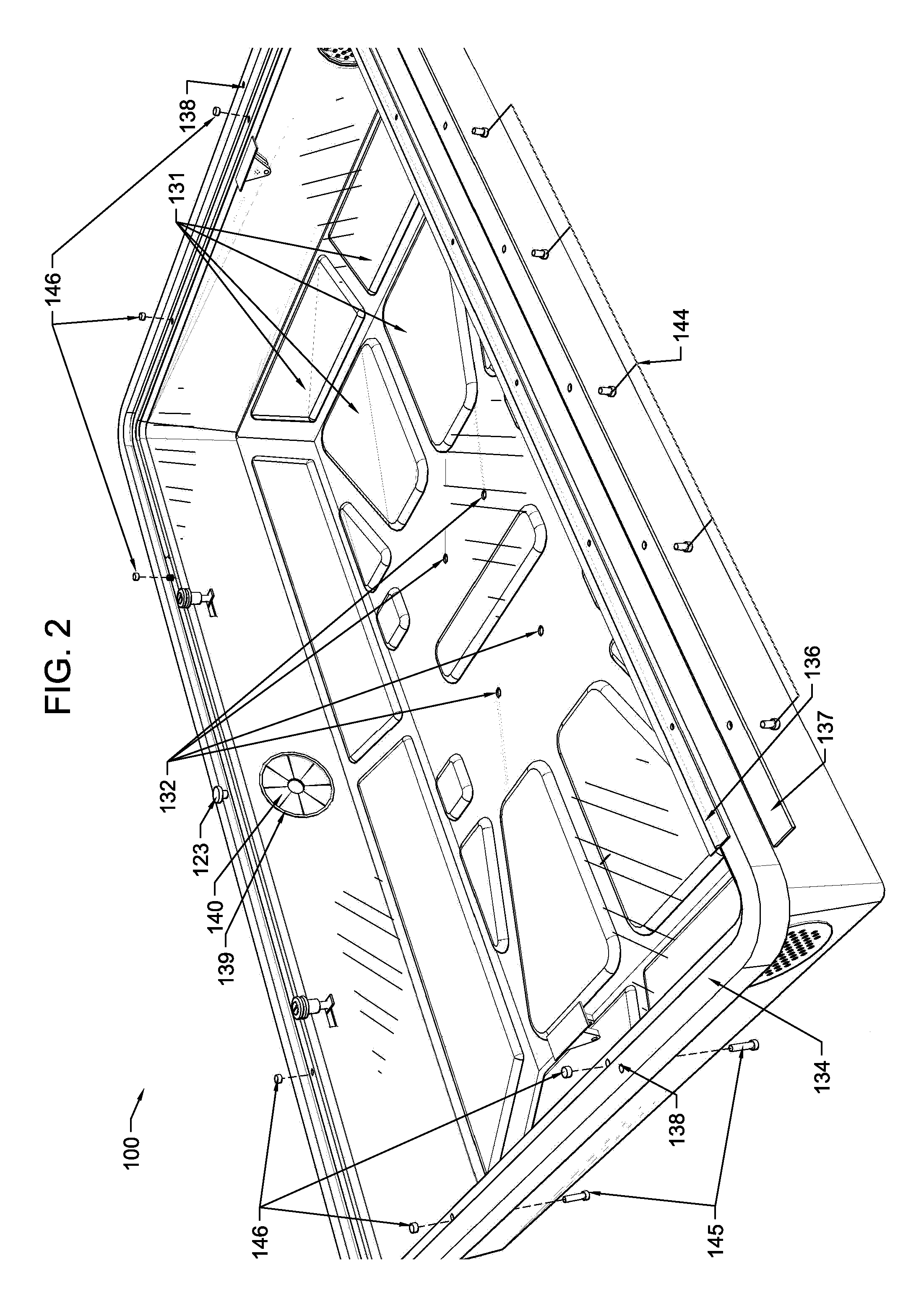
[0018]The front, planar viewing element 120 is constructed of substantially transparent polycarbonate or other suitable transparent material and may include one or more non-reflective, anti-glare surfaces. The rear, recessed containing element 130 is in the general form of a shallow rectangular prism open on one large side. Containing element 130 is constructed from polystyrene, high-density polyethylene, or some similar substance. Containing element 130 may be manufactured using many different techniques, but conventional vacuum-forming technology is preferred. To ensure maximal structural rigidity of the device, a regular network of reinforcing depressions (as exemplified by 131) is formed in the back surface of containing element 130 except at the ...


PUM

PropertyMeasurementUnit
dimensionaaaaaaaaaa
angleaaaaaaaaaa
rigidityaaaaaaaaaa

Abstract

A lightweight, weatherproof, protective enclosure for flat panel displays comprising a containing element in the form of an open, shallow rectangular prism with a regular network of shallow reinforcing depressions formed in its outer surface and a substantially transparent planar viewing element hingedly connected to the containing element such that when the viewing element is closed over, and sealed to, the containing element the protective enclosure forms a lightweight, monocoque structure with enhanced structural rigidity.

Description

CROSS-REFERENCE TO RELATED APPLICATIONS[0001]The present application derives benefit from U.S. Provisional App. No. 61 / 591,392 (“Improved All-Weather Enclosure for Flat Panel Displays”) filed on Jan. 27, 2012.FIELD OF THE INVENTION[0002]The present invention relates to an improved all-weather enclosure for flat panel displays including flat panel televisions.BACKGROUND OF THE INVENTION[0003]Flat panel displays, including flat panel televisions, computer displays, and displays used for digital signage have become far less expensive in recent years leading to the deployment of such devices in a multitude of unconventional physical locations, including exterior locations where they are exposed to the elements. For example, it is not unusual for flat panel televisions be deployed in residential applications in the backyard near the family grill or overlooking the pool.[0004]Unsurprisingly, products have been constructed to enclose these devices and shield them from the elements. Unfortu...

Claims


Application Information

Patent Timeline
Patent Type & Authority Patents(United States)
IPC IPC(8): G02F1/1333G06F1/16H04N5/64G06F1/18G02F1/1335
CPCG06F1/1601G06F1/182H04N5/64G02F1/133608G02F2001/133628G02F1/133628H05K5/03H05K5/0221H05K5/0226H05K5/061H05K5/069H05K7/20136
Inventor KING, JUSTIN
Owner PROTECTIVE ENCLOSURES CO LLC
Why Eureka
Try Eureka