
Device for converting a force or a pressure into an electrical signal and method for producing such a device

Active Publication Date: 2016-01-26
HYDAC ELECTRONICS GMBH
View PDF11 Cites 0 Cited by
  • Summary
  • Abstract
  • Description
  • Claims
  • Application Information

AI Technical Summary

Benefits of technology

The present invention aims to provide an improved device that overcomes the shortcomings of previous generations and ensures reliable operation and high measurement precision. Additionally, the invention provides a method for producing such devices that generate consistent and precise results in simple steps.

Problems solved by technology

From a production engineering perspective, these kinds of sensors are quite complex with regard to the required oil filling step, and they suffer from further disadvantages, for example, the undesired influence of the expansion of the transfer medium on the sensor signal in the event of a temperature increase.

Method used


Image

  • Device for converting a force or a pressure into an electrical signal and method for producing such a device
  • Device for converting a force or a pressure into an electrical signal and method for producing such a device
  • Device for converting a force or a pressure into an electrical signal and method for producing such a device

Examples


Embodiment Construction

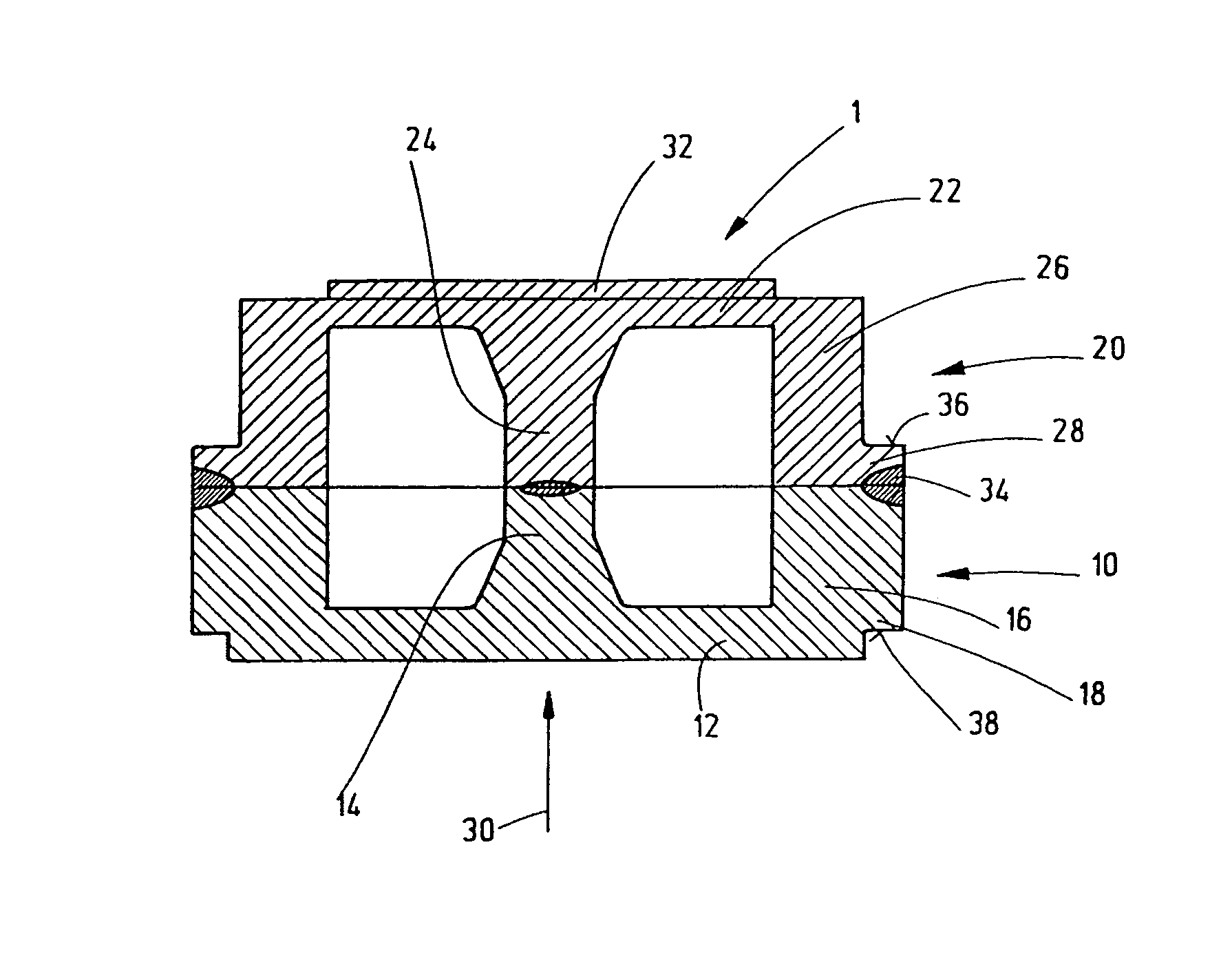
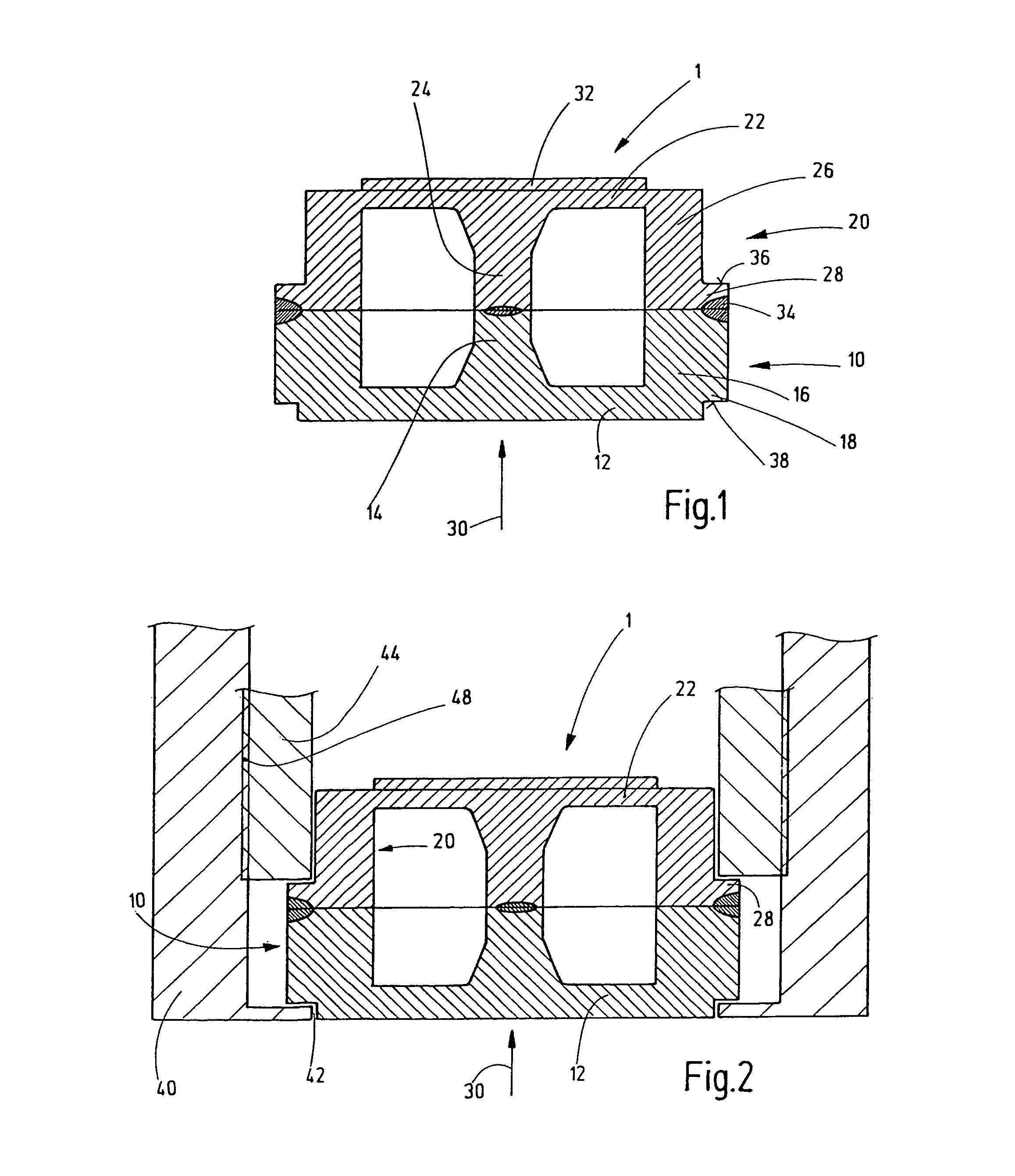
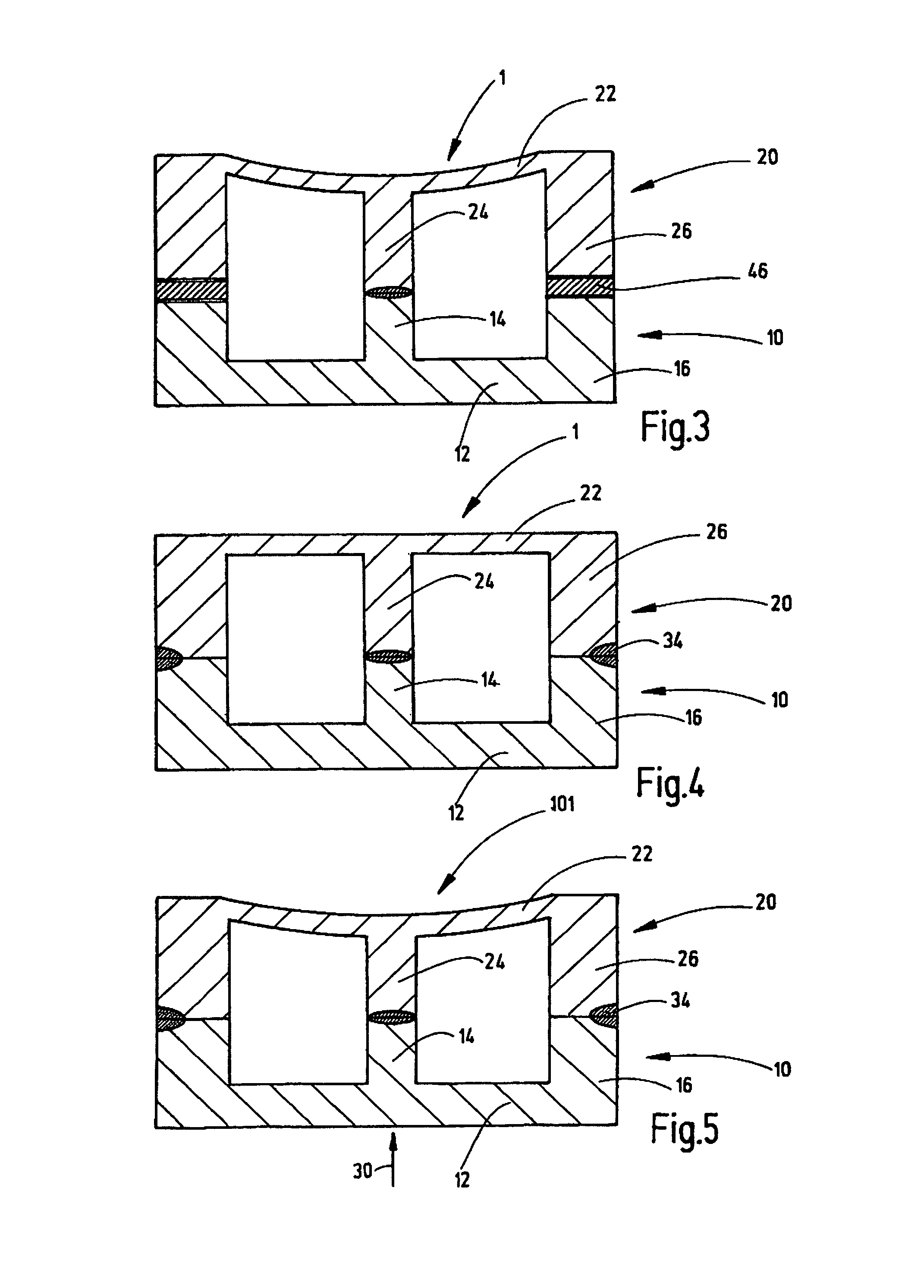
[0026]FIG. 1 shows a cross-section of a first exemplary embodiment of a device 1 according to the invention that includes a first deformation element 10 forming in one piece a first membrane 12. The first deformation element 10 is substantially shaped as a pot in one piece with the membrane 12, a first force transmitter 14 and a circumferential edge 16. The first force transmitter 14 is centrally disposed in the area of the preferably circular first membrane 12, and it is at least in sections cylindrical. The first force transmitter 14 widens in a cone-shaped manner at the transition to the first membrane 12. The transition to the first membrane 12 can additionally be rounded.

[0027]The device 1 includes a second deformation element 20 formed in one piece with a second membrane 22, a second force transmitter 24 and an edge 26. The thickness of the second membrane 22 is less than the thickness of the first membrane 12. The second force transmitter 24 widens at the transition to the se...


PUM

PropertyMeasurementUnit
Forceaaaaaaaaaa
Pressureaaaaaaaaaa
Deformation enthalpyaaaaaaaaaa

Abstract

A device (1) converts a force or a pressure into an electrical signal and has a first deformation element (10), in particular a first membrane (12), to apply the force or the pressure to the device (1) and a second deformation element (20), in particular a second membrane (22), to convert the deflection of the force or the pressure into an electrical signal. The first deformation element (10) has a first force transmitter (14), and the second deformation element (20) has a second force transmitter (24) for transmitting the force from the first deformation element (10) to the second deformation element (20). The first force transmitter (14) is rigidly connected at its end distant from the first deformation element (10) to the end of the second force transmitter (24) distant from the second deformation element (20). Both compressive forces and tensile force can be transmitted from the first deformation element (10) to the second deformation element (20) by the first and second force transmitters (14, 24). A method produces that device.

Description

FIELD OF THE INVENTION[0001]The invention relates to a device for converting a force or a pressure into an electrical signal and a method for producing such a device.BACKGROUND OF THE INVENTION[0002]Devices of this kind are typically based on the fact that the force and / or pressure causes a deformation of a deformation element intended for this purpose. That deformation is converted into an electrical signal. For example, a cantilever beam can be provided for a measurement of pure force, while a membrane is provided for a measurement of pressure.[0003]For certain applications, particularly in the fields of processing and food engineering, a flush-mounted sensor is advantageous, where no medium is able to collect in the otherwise customary connection channel to the deformation element of the apparatus. With such sensors, the deformation of a flush-mounted deformation element, for example a flush-mounted membrane, is usually forwarded by a non-compressible transmission medium, for exa...

Claims


Application Information

Patent Timeline
IPC IPC(8): G01L1/00G01L1/18G01L1/22G01L9/00
CPCG01L1/18G01L1/2231G01L9/006Y10T29/49002
Inventor BRODE, WOLFGANGKEINER, ANDRE
Owner HYDAC ELECTRONICS GMBH
Learn More