
Radio frequency identification in safety applications

a radio frequency identification and safety technology, applied in vehicle position/course/altitude control, using reradiation, instruments, etc., can solve problems such as triggering faults when moving objects, and achieve the effect of safe control and minimizing collisions

Active Publication Date: 2016-01-26
ROCKWELL AUTOMATION TECH
View PDF7 Cites 1 Cited by
  • Summary
  • Abstract
  • Description
  • Claims
  • Application Information

AI Technical Summary

Benefits of technology

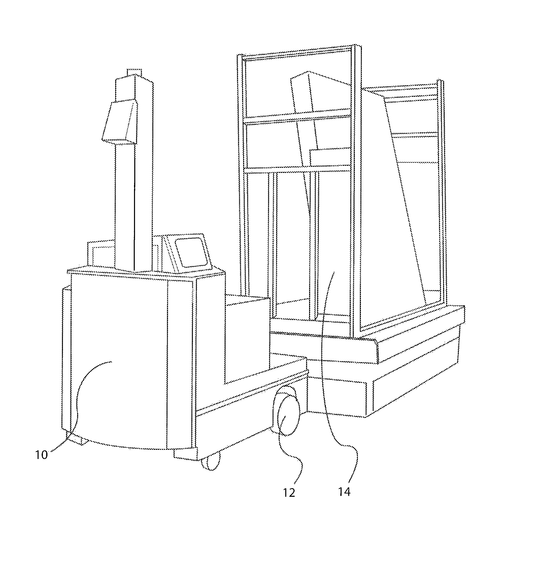
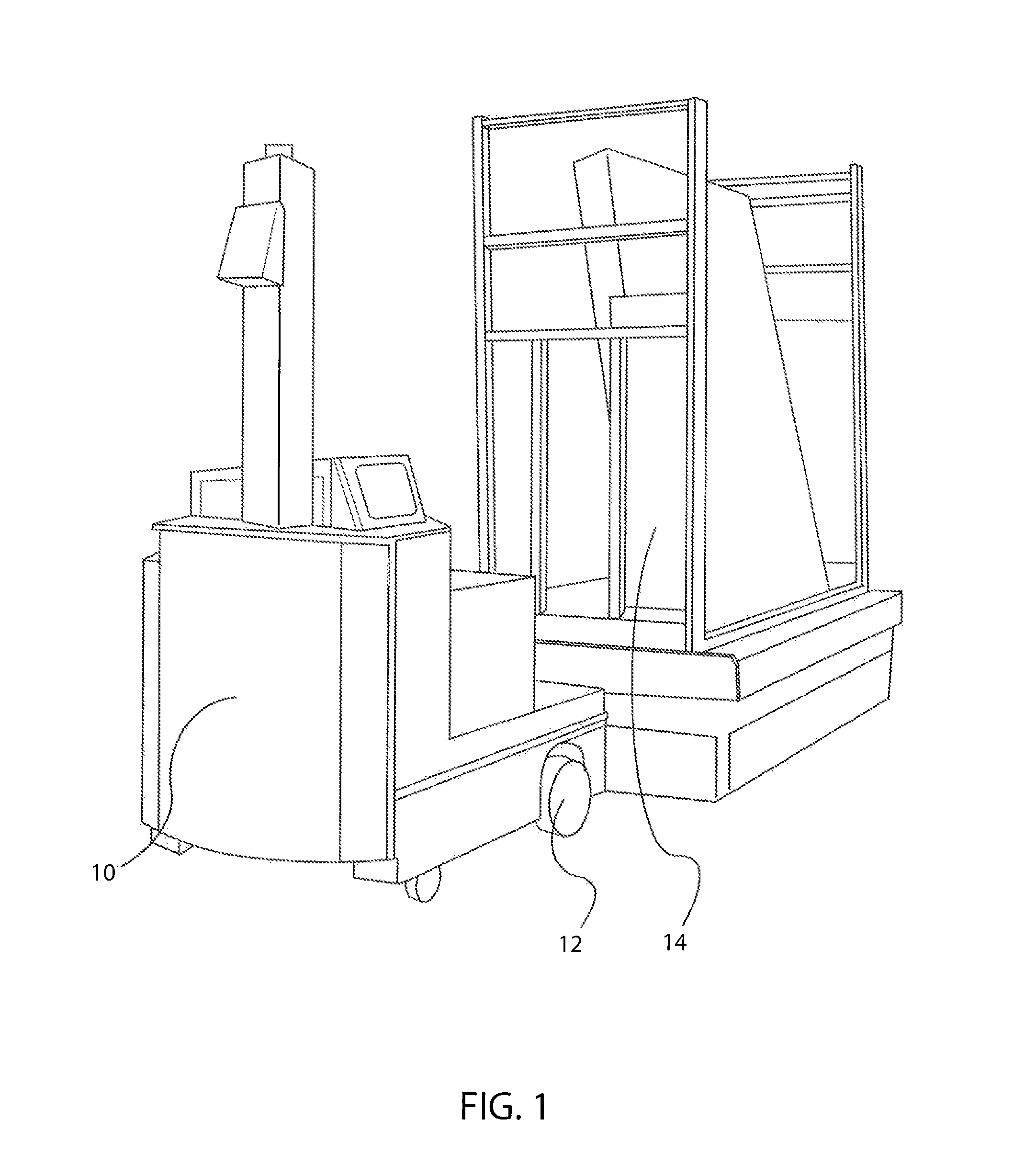
[0005]The present inventors have recognized that an RFID system may be used for safely controlling AGV's, such as in a field, warehouse, factory or industrial environment. As described herein, an AGV may utilize locally stored information about the RFID system in conjunction with an RFID transceiver or antenna for detecting radio frequency identification tags in proximity and allowing safe movement between locations. If personnel are identified via other technology with the area, the safety control system may stop the AGV or all AGV's in the area. As such, a Safety Integrity Level 2 (“SIL 2”) or Performance Level d (“PLd”) characteristic may be achieved, such as in accordance with IEC / EN 62061, “Safety of machinery: Functional safety of electrical, electronic and programmable electronic control systems,” and EN ISO 13849-1:2008, each describing safety-related electrical control systems and which documents are hereby expressly incorporated by reference, by minimizing collisions and thus potential injury and damage.
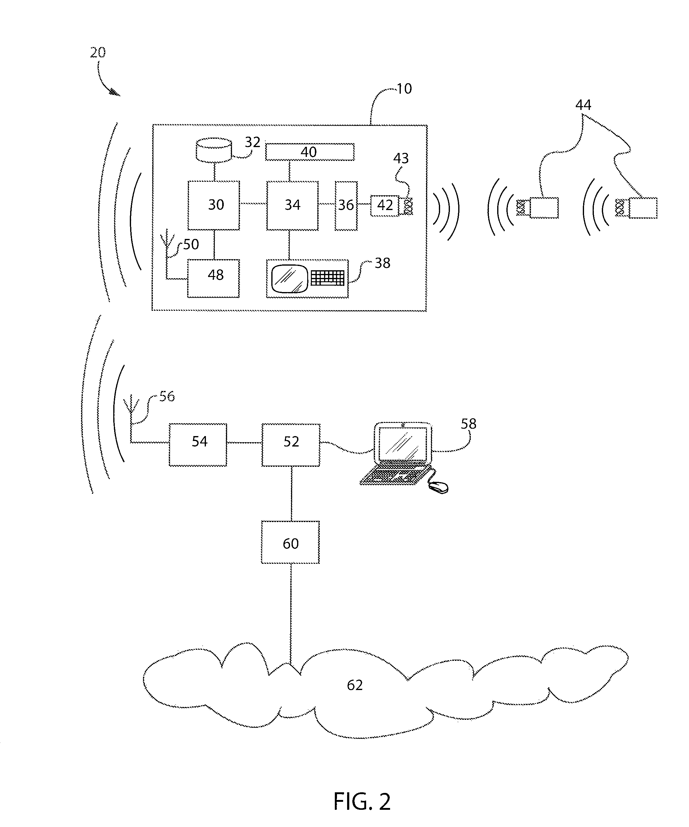
[0006]Aspects of the present invention provide a moving object with a processor executing a program stored in a non-transitory computer-readable storage medium and having a radio frequency identification transceiver or antenna for communicating with a plurality of radio frequency identification tags, wherein the program instructs the processor to perform the following steps: (a) read a first memory location from a radio frequency identification tag in proximity, the first memory location storing a unique identification; (b) compare the first memory location with a plurality of first data elements stored in a predetermined table, each of the first data elements associated with a particular radio frequency identification tag; (c) safely determine a current position of the moving object upon successfully matching the first memory location with a first data element; and (d) trigger a fault upon failing to match the first memory location with a first data element.
[0012]Another embodiment may similarly provide a method for safely controlling a moving object using radio frequency identification comprising: (a) reading a first memory location from a radio frequency identification tag in proximity, the first memory location storing a unique identification; (b) comparing the first memory location with a plurality of first data elements stored in a predetermined table, each of the first data elements associated with a particular radio frequency identification tag; (c) safely determining a current position of the moving object upon successfully matching the first memory location with a first data element; and (d) triggering a fault upon failing to match the first memory location with a first data element.
[0013]Yet another embodiment may similarly provide radio frequency identification system for safely controlling a moving object comprising: a plurality of radio frequency identification tags, each storing a unique identification in a first memory location; and a moving object having a radio frequency identification transceiver or antenna for communicating with each of the plurality of radio frequency identification tags and a processor with a non-transitory computer-readable storage medium containing a predetermined table comprising a plurality of first data elements, each of the first data elements associated with a particular radio frequency identification tag. The moving object may read a first memory location from a radio frequency identification tag in proximity, safely determine a current position upon successfully matching the first memory location with a first data element, and trigger a fault upon failing to match the first memory location with a first data element.

Problems solved by technology

The moving object may trigger a fault if the first memory location read from the next radio frequency identification tag in proximity fails to match the prediction.

Method used


Image

  • Radio frequency identification in safety applications
  • Radio frequency identification in safety applications
  • Radio frequency identification in safety applications

Examples


Embodiment Construction

[0025]One or more specific embodiments of the present invention will be described below. It is specifically intended that the present invention not be limited to the embodiments and illustrations contained herein, but include modified forms of those embodiments including portions of the embodiments and combinations of elements of different embodiments as come within the scope of the following claims. It should be appreciated that in the development of any such actual implementation, as in any engineering or design project, numerous implementation-specific decisions must be made to achieve the developers' specific goals, such as compliance with system-related and business related constraints, which may vary from one implementation to another. Moreover, it should be appreciated that such a development effort might be complex and time consuming, but would nevertheless be a routine undertaking of design, fabrication, and manufacture for those of ordinary skill having the benefit of this...


PUM


Abstract

Aspects of the present invention provide an RFID system for safely controlling an auto guided vehicle, an automated robot or other moving object (“AGV”). The system may include a plurality of radio frequency identification (“RFID”) tags, and each may store a unique identification in a first memory location, a position in a second memory location and / or an instruction in a third memory location. An AGV having an RFID transceiver or antenna and a computer with a non-transitory computer-readable storage medium containing a predetermined table may read one or more of the memory locations. The table comprises a plurality of data elements with certain data elements associated with particular RFID tags. The AGV safely determines its location upon matching the one or more memory locations read with one or more data elements, or triggers a fault upon failing to match. The AGV may also predict the next RFID tag.

Description

BACKGROUND OF THE INVENTION[0001]The present invention relates to radio frequency identification (“RFID”) in safety applications, and in particular, to an RFID system for safely controlling an auto guided vehicle, an automated robot or other moving object (“AGV”).[0002]RFID tags are typically used to detect the presence or identity of a physical object wherein an RFID tag is attached to the physical object. RFID tags may also be used to determine the location of a moving object in an RFID system wherein an RFID tag is attached to a stationary object at a particular location and detection of the RFID tag via an RFID transceiver on the moving object indicates proximity of the moving object to the stationary object at the particular location.[0003]RFID tags are typically small, passive devices in which, upon coming into proximity of an electromagnetic field produced by an RFID transceiver or antenna, the RFID tag energizes and transmits via radio frequency waves data held in the RFID t...

Claims


Application Information

Patent Timeline
Patent Type & Authority Patents(United States)
IPC IPC(8): G01S1/68G01S5/14G01S13/87G06K17/00G05D1/02G01S13/75G01S5/02
CPCG01S5/14G01S13/876G06K17/00G01S1/68G01S5/0289G01S13/751G05D1/0274
Inventor ZOMCHEK, KEVIN M.JONES, DEREK W.WALTZ, WILLIAM E.BOYD, RICHARD W.FOSTER, WAYNE
Owner ROCKWELL AUTOMATION TECH
Learn More