Regenerative braking safety system and method of use

a safety system and braking technology, applied in the direction of motor/generator/converter stopper, dynamo-electric converter control, centrifuge, etc., can solve the problem of converting the torque applied to the load, returning a significant amount of electrical power to the power grid, and maintaining the power of the instrument itsel

Active Publication Date: 2016-01-26
BECKMAN COULTER INC
View PDF21 Cites 2 Cited by
  • Summary
  • Abstract
  • Description
  • Claims
  • Application Information

AI Technical Summary

Benefits of technology

[0012]In an embodiment of the above aspect, the motor is an AC induction motor driven by a rotating magnetic field and wherein the power cut-off is configured to de-energize the rotating magnetic field when the electrical system is decoupled from the power source. In another embodiment, the electrical system includes a shunt circuit to safely dissipate the recovered energy, wherein the power cut-off is configured to redirect the recovered energy to the shunt circuit when the electrical system is decoupled from the power source. In yet another embodiment, the electrical system includes a plug to reversibly couple the electrical system to a power outlet of the power source, wherein the power cut-off is configured to disable the effect of regenerative braking of the motor when the plug is unplugged from the power outlet. In still another embodiment, the power cut-off is configured to prevent recovered power from reaching the plug when the plug is unplugged from the power outlet.
[0020]In another aspect, the technology relates to a method of safely dissipating electrical energy during the shut-down of a centrifuge having a motor capable of generating electrical energy, the method including: monitoring an output value associated with the electrical energy generated by the motor; disconnecting the centrifuge from an external power source to shut-down the centrifuge; detecting the disconnect from the external power source as a characteristic change in the monitored output value; and routing the electrical energy generated by the motor to a shunt circuit that bypasses an external power plug of the centrifuge.

Problems solved by technology

This slip translates into the amount of torque applied to the load.
Depending on the type of instrument containing the ACIM, the amount of energy generated during motor deceleration may be large enough that it can not only maintain power to the instrument itself for some period of time, but also return a significant amount of electrical power to the power grid.
This situation could be potentially dangerous.
Furthermore, while it is regenerating power, the instrument may also be presenting hazardous voltages to the user, as it is designed to return power to the power grid, and the plug has become a live power terminal.
Additionally, in certain circuits that detect electrical faults or other safety-critical conditions, software in the system may attempt to trip a circuit breaker via a relay if certain conditions are met.
System software may attempt to turn off the breaker, but regenerative braking will keep the instrument running, thereby continuing instrument operation even in a potentially dangerous condition.
It has been determined that the two safety mechanisms described above may not adequately provide protection throughout the regenerative braking cycle of an instrument.
If disconnected from AC power during this portion of the regenerative braking cycle, unsafe situations could arise.

Method used


Image

  • Regenerative braking safety system and method of use
  • Regenerative braking safety system and method of use
  • Regenerative braking safety system and method of use

Examples


Embodiment Construction

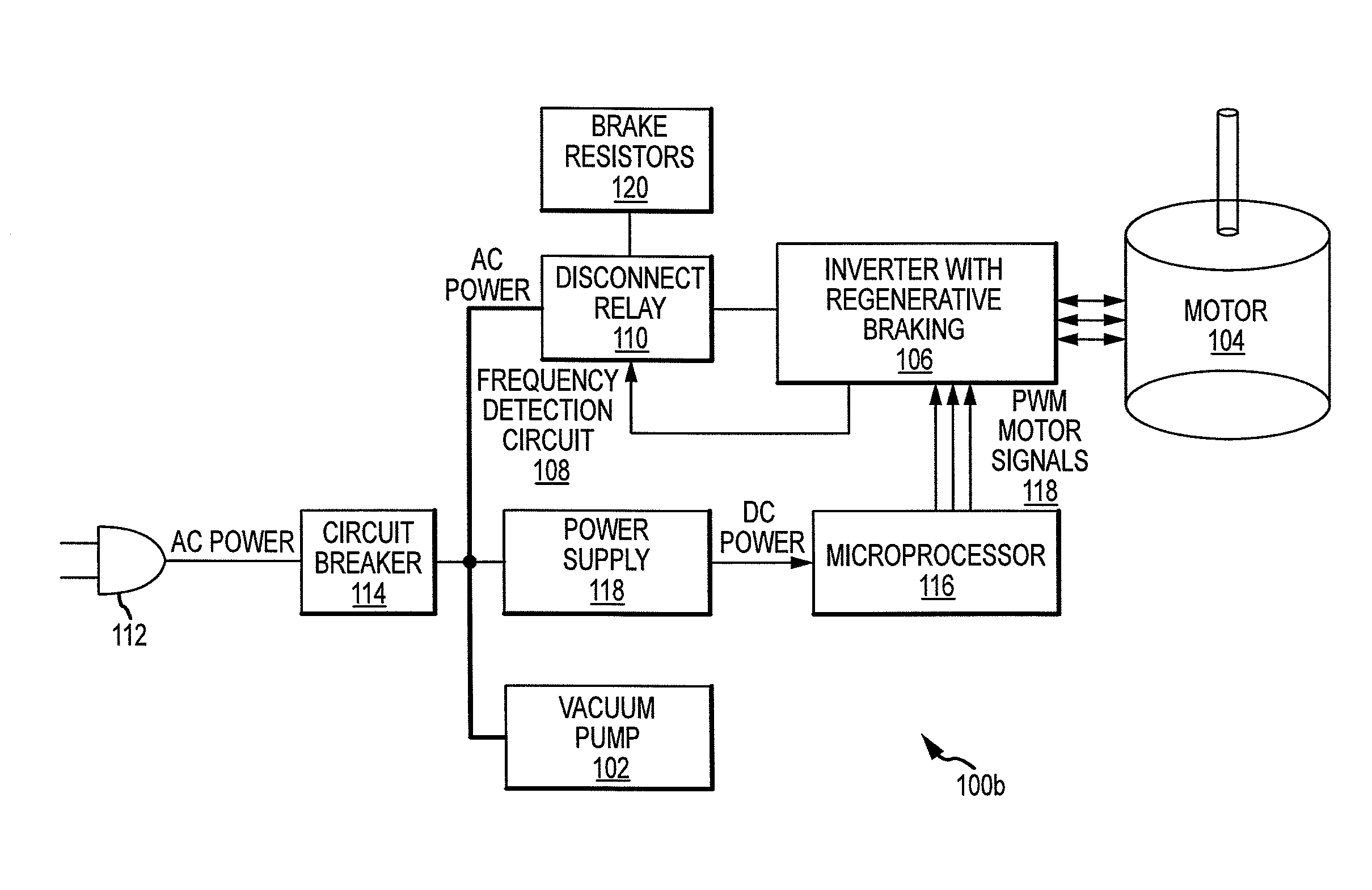
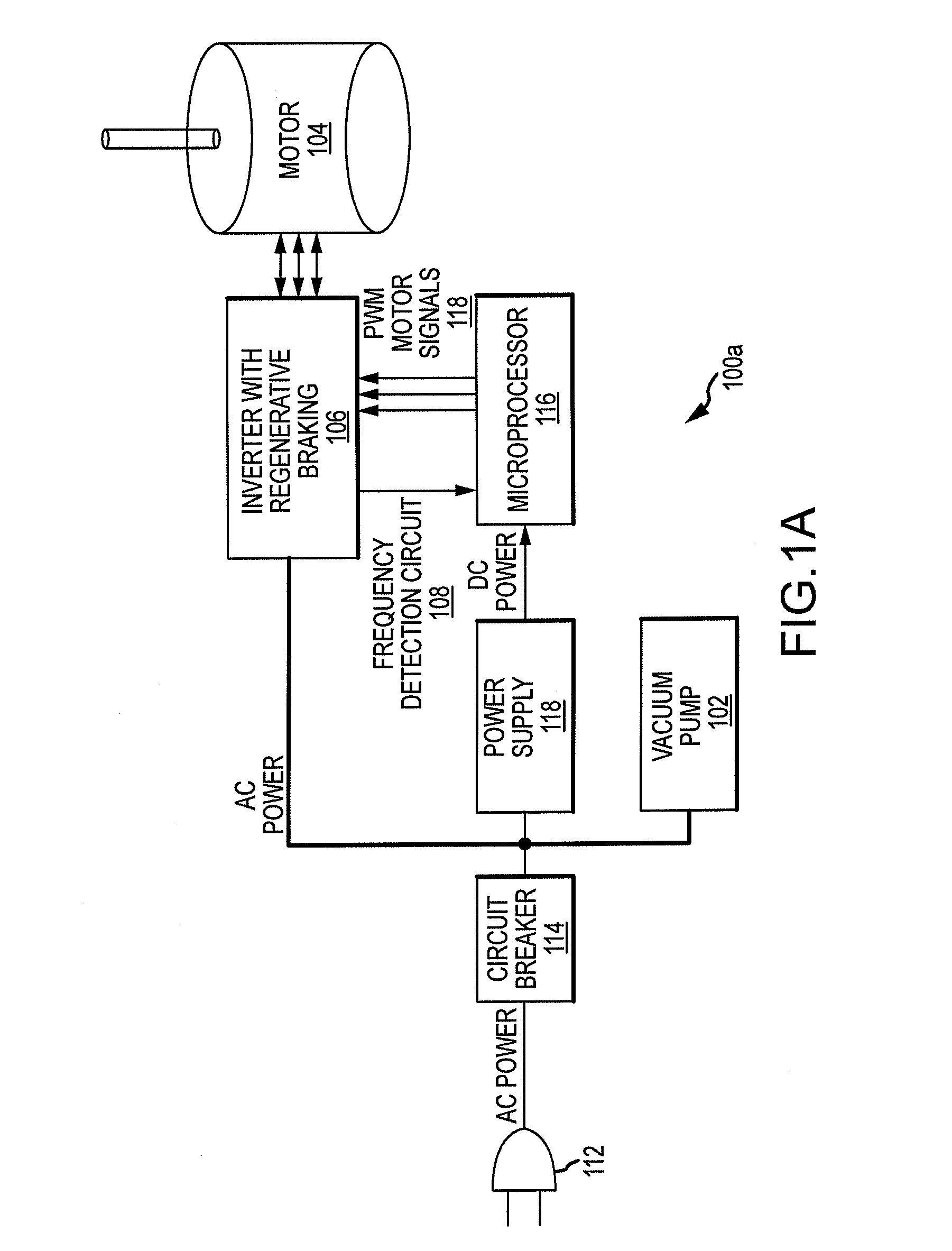
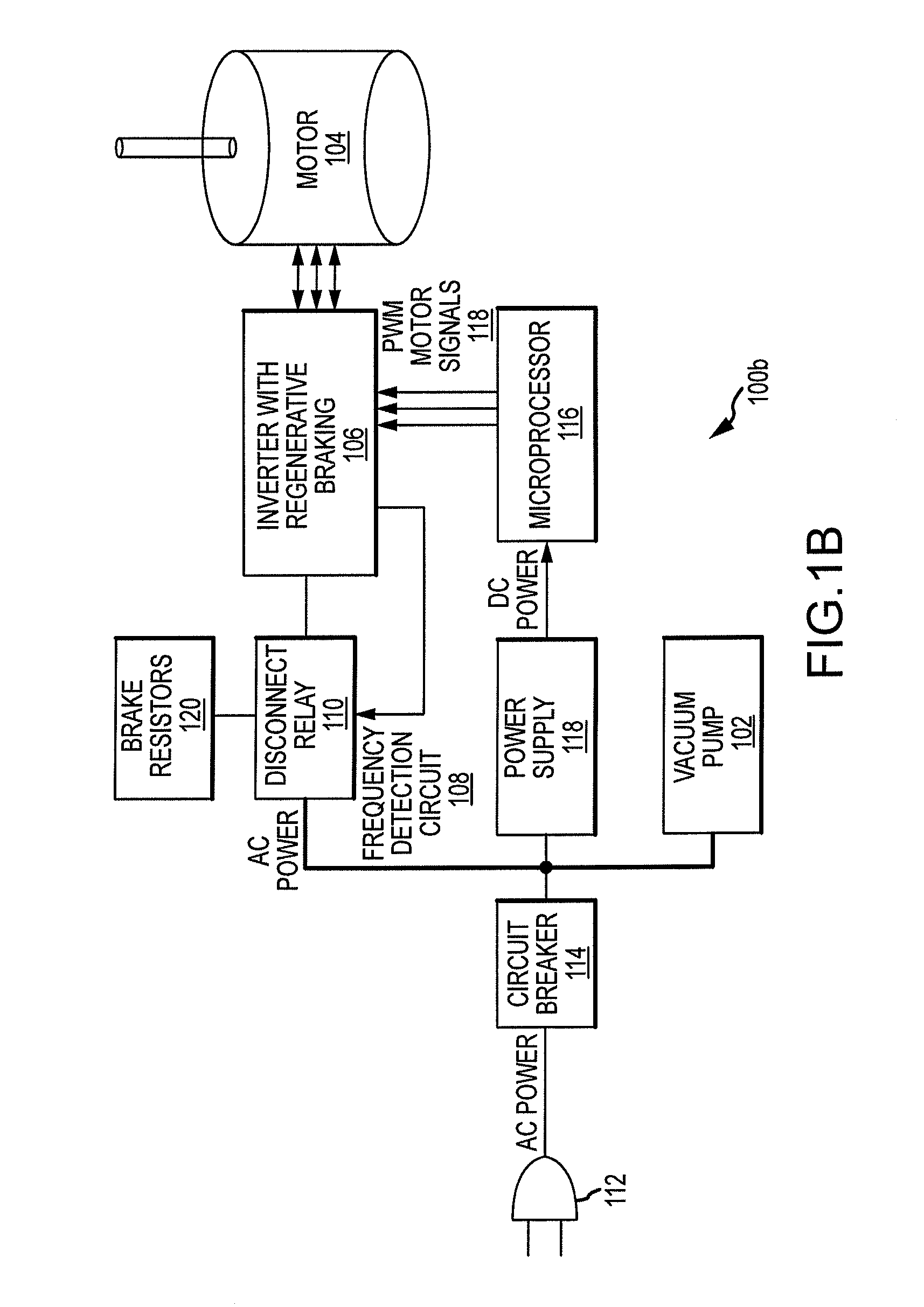
[0026]The present disclosure describes a regenerative braking safety system and method. For the purposes of the present disclosure, the systems and methods described herein will be described primarily in a centrifuge embodiment, that is, as being incorporated into a centrifuge instrument having a regenerative braking system. A centrifuge is an instrument that creates a force on an object, such as a laboratory sample, by rapidly rotating the object around a fixed axis. Centrifuges typically involve the rotation of a large mass at high speeds and, thus, inherently have a significant amount of stored kinetic energy when they are turned off that can be recovered via regenerative braking. However, the reader should understand that this is but one embodiment of an instrument with regenerative braking and that the systems and methods described herein are broadly applicable to any piece of equipment that both receives power from an external source and can generate power from regenerative br...


PUM


Abstract

A centrifuge includes a regenerative braking safety system including an electrical system reversibly coupled to a power source. A motor is coupled to the electrical system. The motor is capable of driving a rotor using power delivered through the electrical system, and is further capable of supplying the electrical system with recovered energy. The recovered energy is electrical energy converted from kinetic energy of the rotor during regenerative braking of the motor. The safety system includes a power cut-off configured to disable the effect of regenerative braking of the motor when the electrical system is decoupled from the power source.

Description

CROSS-REFERENCE TO RELATED APPLICATIONS[0001]This application claims priority to and the benefit of U.S. Provisional Patent Application Ser. No. 61 / 442,703, filed Feb. 14, 2011, entitled “Regenerative Braking Safety System and Method of Use,” the disclosure of which is hereby incorporated by reference herein in its entirety.INTRODUCTION[0002]An AC induction motor (ACIM) works by controlling “slip,” which is the difference between the rotating magnetic field frequency and the actual motor rotational frequency. This slip translates into the amount of torque applied to the load. When decelerating an ACIM, this slip becomes negative and the ACIM turns into an energy generator as rotational or kinetic energy is converted into electrical energy. In previous centrifuge designs, this energy has typically been dissipated in “brake resistors” that generate heat. Due to the current economic and energy-conscious environment, the preference of the market is to return this extra energy to the pow...

Claims


Application Information

Patent Timeline
Patent Type & Authority Patents(United States)
IPC IPC(8): H02K7/10B04B9/10H02P29/04H02P29/02H02P3/14H02J3/38
CPCH02P29/04B04B9/10H02P3/14H02P29/025H02J3/383Y02E10/563H02J2300/24H02J3/381Y02E10/56
Inventor KEEN, RONALD T.HESSLER, JASON L.
Owner BECKMAN COULTER INC
Why Eureka
Try Eureka