Chopper amplifier

a technology of amplifier and chopper, which is applied in the direction of amplifier with semiconductor device/discharge tube, dc-amplifiers with dc-coupled stages, and differential amplifiers to achieve the effect of removing residual offs

Active Publication Date: 2016-01-26
RICOH KK
View PDF10 Cites 2 Cited by
  • Summary
  • Abstract
  • Description
  • Claims
  • Application Information

AI Technical Summary

Benefits of technology

[0014]The present invention aims to provide a chopper amplifier which can remove residual offsets.

Problems solved by technology

However, there is a problem with the chopper amplifier that a residual offset applied to a voltage of the output OUT of the LPF due to clock feedthrough occurring when the Nch transistor switches of the chopper modulator 1 are transited from a non-conductive state to a conductive state.
This is mainly caused by a mismatch between the output resistances of the signal source and the bias source, that between the gate-source capacitances of the transistor switches, or that between the input capacitances of the two input terminals of the amplifier.

Method used


Image

  • Chopper amplifier
  • Chopper amplifier
  • Chopper amplifier

Examples


first embodiment

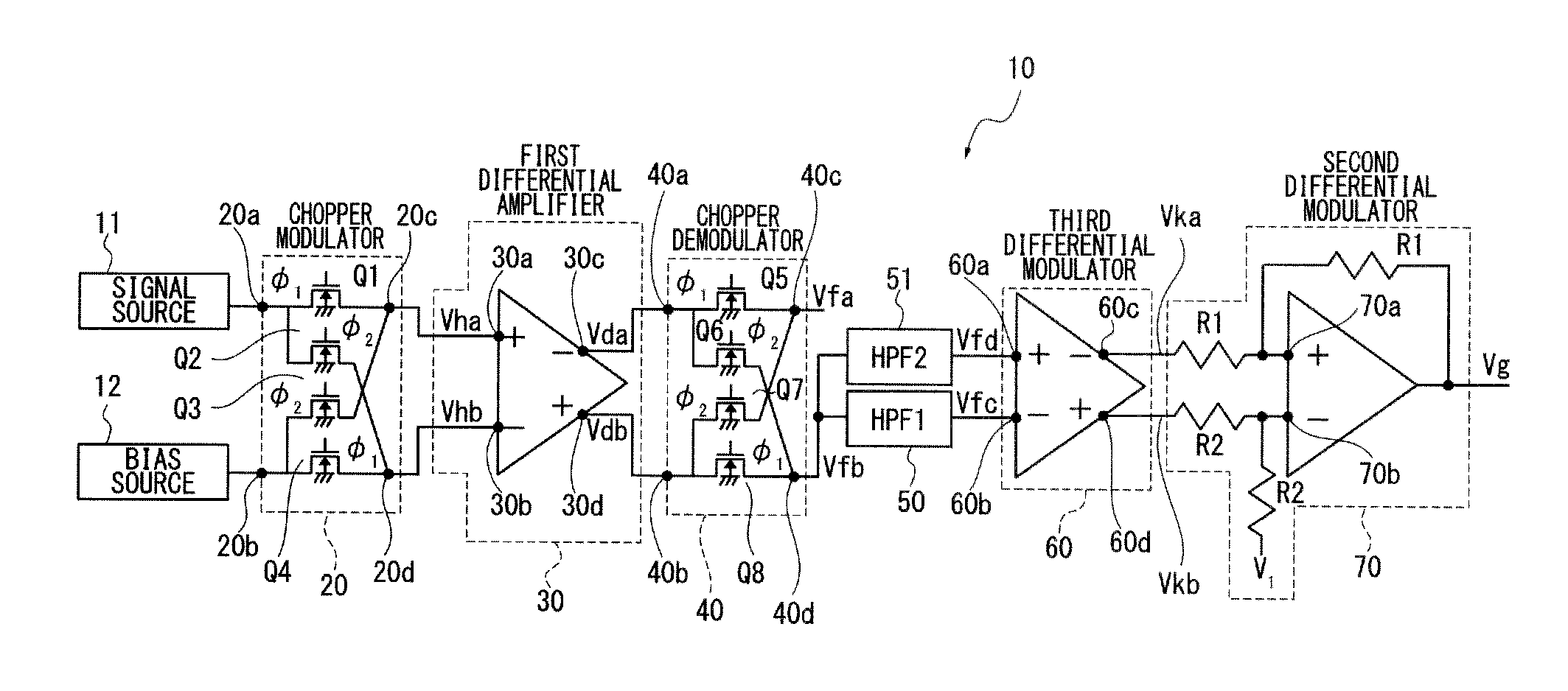
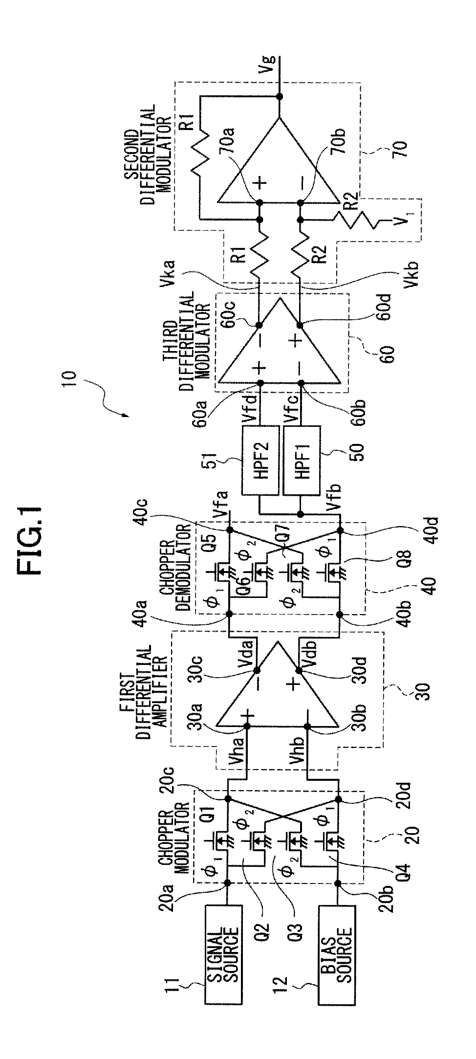
[0026]FIG. 1 shows the structure of a chopper amplifier 10. The chopper amplifier 10 comprises a chopper modulator 20 to modulate a detection signal from a signal source 11 and a bias voltage as a certain DC voltage from a bias source 12 and a differential amplifier 30 to differentially amplify a voltage or chopper modulation signal output from the chopper modulator 20.

[0027]The chopper amplifier 10 further comprises a chopper demodulator 40 to demodulate a differential output voltage from the first differential amplifier 30 and output a demodulation signal, first and second highpass filters 50, 51 to cut off a low frequency component of the demodulation signal from the chopper demodulator 40 and output a modulation signal, a third differential amplifier 60 to differentially amplify the modulation signal from the highpass filters 50, 51, and a second differential amplifier 70 to differentially amplify a differential modulation signal from the third differential amplifier 60.

[0028]Th...

second embodiment

[0055]Another example of first and second highpass filters are described referring to FIG. 4. First and second highpass filters comprise capacitors C1, C2 and MOS transistors Tr1, Tr2, respectively.

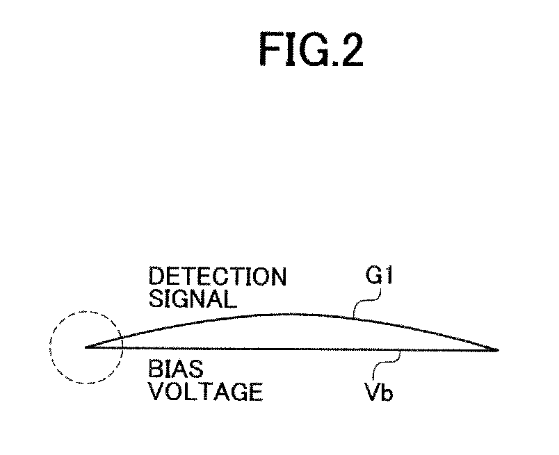
[0056]The cutoff frequency of the first highpass filter needs to be set to a low value due to the low frequency band of the detection signal G1. For example, considering the capacitance and resistance of a 1st order highpass filter with cutoff frequency of 1 Hz, when capacitance is set to 1 pF, the highpass filter requires resistance of 160 GΩ. In general a resistance of 160 GΩ made of a polysilicon element on a semiconductor substrate requires an enormous area.

[0057]In view of this, to realize a highpass filter with a smaller area and a low cutoff frequency, a very large-resistance element can be formed by setting a gate-source voltage Vgs of the MOS transistor Tr1 to a threshold voltage or less. This is because the smaller the voltage Vgs, the larger the resistance the MOS transistor Tr...


PUM


Abstract

A chopper amplifier includes a chopper modulator to modulate a certain detection signal and a bias voltage by a certain control signal and output a chopper modulation signal, a first differential amplifier to differentially amplify the chopper modulation signal from the chopper modulator and output a differential modulation signal, a chopper demodulator to demodulate the differential modulation signal from the first differential amplifier by the control signal and output a demodulation signal, a second differential amplifier to extract a detection signal component from the demodulation signal, and a plurality of filters connected at an input terminal of the second differential amplifier and having different cutoff frequencies from each other relative to the demodulation signal.

Description

CROSS REFERENCE TO RELATED APPLICATION[0001]The present application is based on and claims priority from Japanese Patent Application No. 2013-90371, filed on Apr. 23, 2013, the disclosure of which is hereby incorporated by reference in its entirety.BACKGROUND OF THE INVENTION[0002]1. Field of the Invention[0003]The present invention relates to a chopper amplifier which amplifies a finite, low-frequency signal.[0004]2. Description of the Related Art[0005]In related art Japanese Patent Application Publication No. 2006-279377 discloses a chopper amplifier to amplify a finite, low frequency detection signal, for example.[0006]Such a chopper amplifier comprises a chopper modulator to modulate a finite, low-frequency input signal by a certain control signal and output a modulation signal, a differential amplifier to differentially amplify the modulation signal, and a chopper demodulator to demodulate the differentially amplified modulation signal in accordance with the control signal for ...

Claims


Application Information

Patent Timeline
Patent Type & Authority Patents(United States)
IPC IPC(8): H03F1/02H03F3/393H03F3/45H03F3/185
CPCH03F3/185H03F3/393H03F3/45995H03F2200/271H03F2200/333
Inventor NAGAHISA, TAKESHI
Owner RICOH KK
Why Eureka
Try Eureka