
Force measuring device

A force-measuring device and force-measuring technology, which are applied in the directions of measurement device, force measurement, magnetic performance measurement, etc., can solve the difficulty in finding the balance position of the vibrator 12 and the stator 11, the difficulty in measurement, the difficulty in the design and adjustment of the vibrator 12 and the stator 11, etc. problem, to achieve the effect of easy deformation, increased sensitivity, convenient design and adjustment

Pending Publication Date: 2022-03-29
SUZHOU THOR ELECTRONIC TECH CO LTD
View PDF0 Cites 1 Cited by
  • Summary
  • Abstract
  • Description
  • Claims
  • Application Information

AI Technical Summary

Problems solved by technology

[0005] It can be understood that the force between the vibrator 12 and the stator 11 is affected by many factors, such as the size of the magnet, the size of the magnetic force level, and the distance between the vibrator 12 and the stator 11. At present, there is no convenient The device for testing the force between the vibrator 12 and the stator 11 is difficult to find the balance position between the vibrator 12 and the stator 11, and it is very difficult to design and adjust the vibrator 12 and the stator 11
[0006] To sum up, there is no force measuring device in the prior art that can conveniently test the magnetic force between two test pieces at different distances, and measure the force between the vibrator 12 and the stator 11 waiting for the test piece more difficult

Method used


Image

  • Force measuring device
  • Force measuring device
  • Force measuring device

Examples


Embodiment Construction

[0050] In order to make the above-mentioned purpose, features and advantages of the present application more obvious and understandable, the specific implementation manners of the present application will be described in detail below in conjunction with the accompanying drawings. It should be understood that the specific embodiments described here are only used to explain the present application, but not to limit the present application. In addition, it should be noted that, for the convenience of description, only some structures related to the present application are shown in the drawings but not all structures. Based on the embodiments in this application, all other embodiments obtained by persons of ordinary skill in the art without making creative efforts belong to the scope of protection of this application.

[0051] The terms "comprising" and "having" and any variations thereof in this application are intended to cover a non-exclusive inclusion. For example, a process, m...


PUM


Abstract

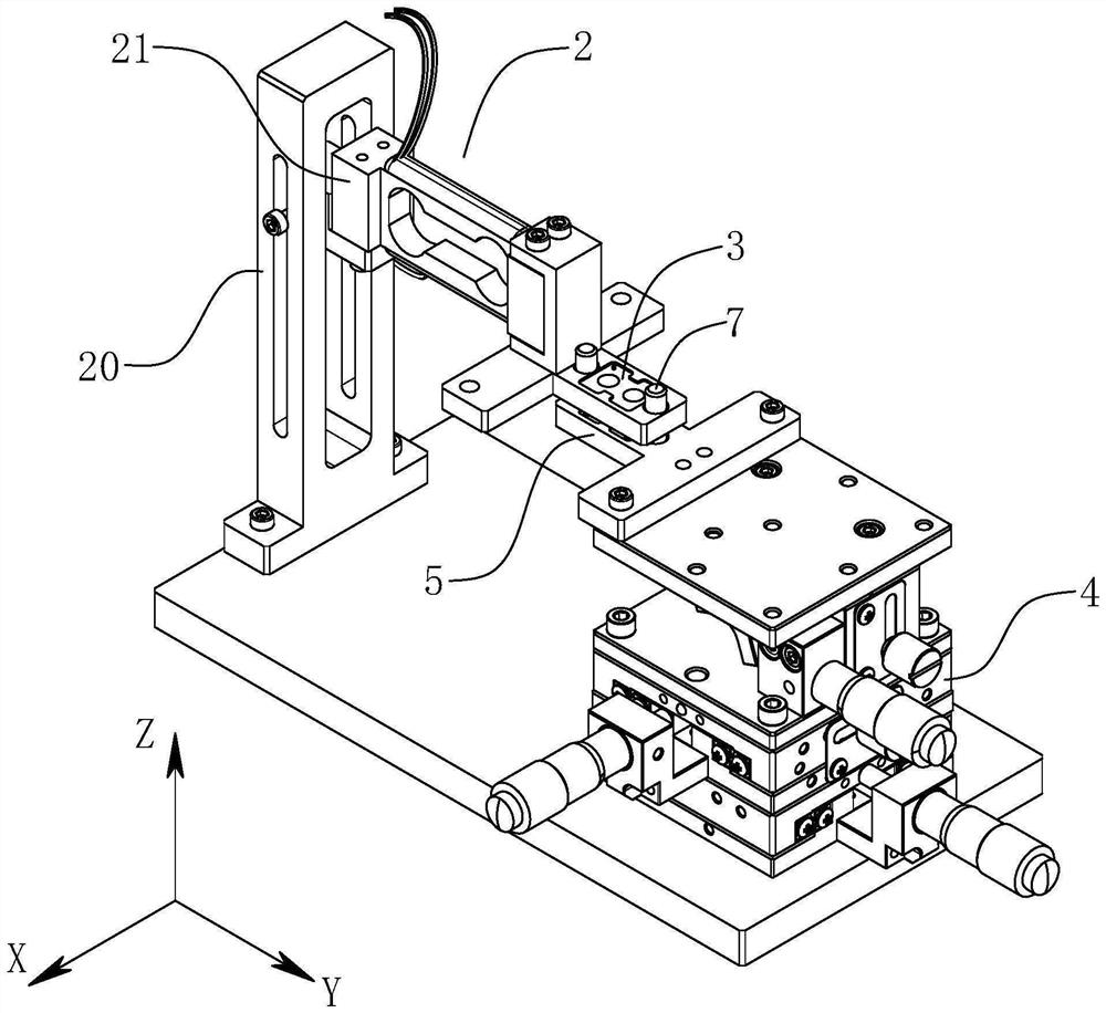
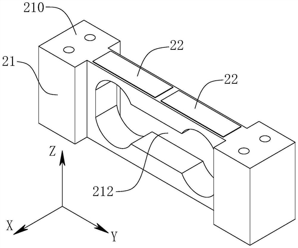
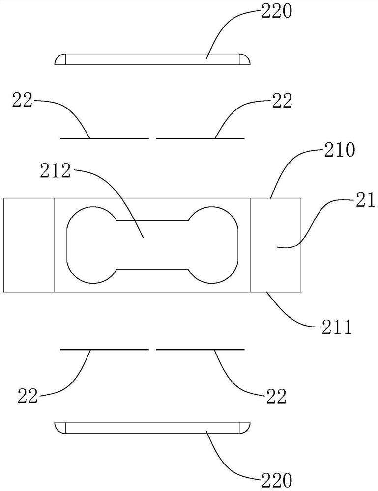
The invention discloses a force measuring device which comprises a force measuring assembly which comprises a support, a force measuring frame connected with the support and a strain detection circuit, and the strain detection circuit comprises a strain gauge arranged on the force measuring frame; the first jig is connected with the force measuring frame and is used for fixing a first piece to be measured; the adjusting module is fixed relative to the bracket; the first jig is connected with the adjusting module and used for fixing a first to-be-tested piece, the second jig is connected with the adjusting module and used for fixing a second to-be-tested piece, the first to-be-tested piece and the second to-be-tested piece are oppositely arranged, and a magnetic force effect exists between the first to-be-tested piece and the second to-be-tested piece; the adjusting module is used for adjusting the distance between the second to-be-tested piece and the first to-be-tested piece. The force measuring device can conveniently measure the magnetic force between the two pieces to be measured, and the measuring precision is high.

Description

technical field [0001] The invention relates to the technical field of mechanical testing, in particular to a force measuring device. Background technique [0002] In vibration devices such as linear vibration motors and bone conduction sounding devices, a vibration unit is often provided. After the coil is energized, the vibration unit can generate vibration under the action of the magnetic force of the coil. [0003] E.g, Figure 11 A structural schematic diagram of a bone conduction sounding device is shown, the bone conduction sounding device includes a casing 1, a vibration unit and a shrapnel 10 both arranged in the casing 1, the vibration unit includes a stator 11 and a vibrator 12 arranged oppositely, wherein, The stator 11 includes a magnetically permeable plate 110 fixedly connected to the housing 1 and a first magnet 111 and a coil 112 connected to the magnetically permeable plate 110 , and the vibrator 12 includes a magnetically permeable bowl 120 and a second ma...

Claims


Application Information

Patent Timeline
Patent Type & Authority Applications(China)
IPC IPC(8): G01L1/22G01R33/12
CPCG01L1/2262G01R33/12
Inventor 陆玉云陶志勇沈佳龙
Owner SUZHOU THOR ELECTRONIC TECH CO LTD
Learn More