Enclosed power clamp

a power clamp and enclosed technology, applied in the field of clamps, can solve the problems of reducing reliability and shortening the life cycle of the power clamp in the manufacturing environmen

Inactive Publication Date: 2004-06-29
DELAWARE CAPITAL FORMATION INC
View PDF2 Cites 2 Cited by
  • Summary
  • Abstract
  • Description
  • Claims
  • Application Information

AI Technical Summary

Benefits of technology

Yet a further object of the present invention is to provide a power clamp that will have all link arms within the clamp mechanism flat, thus removing any offset bends.
Still yet another advantage of the present invention is the use of a breather area along the piston rod to prevent pressure buildup inside the clamp and accidental expulsion of internal lubricating grease.

Problems solved by technology

During operation of the prior art power clamps in the manufacturing environment, such as those found in the automotive industry, weld slag and other debris can contaminate the clamp thus reducing its reliability and shortening its life cycle in the manufacturing environment.
Furthermore, the use of the open link design power clamps may require protective shielding to be placed around the linkage of the clamp, to try and prevent any damage to the linkage of the clamp by spurious contaminates or collisions by other equipment.

Method used


Image

  • Enclosed power clamp
  • Enclosed power clamp
  • Enclosed power clamp

Examples


Embodiment Construction

)

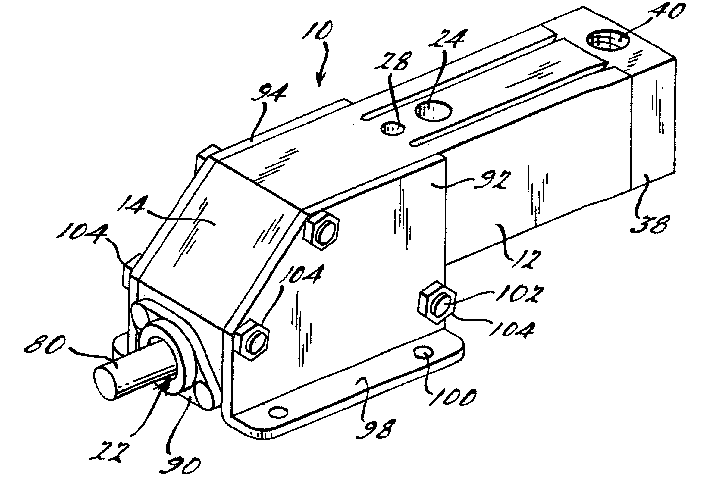
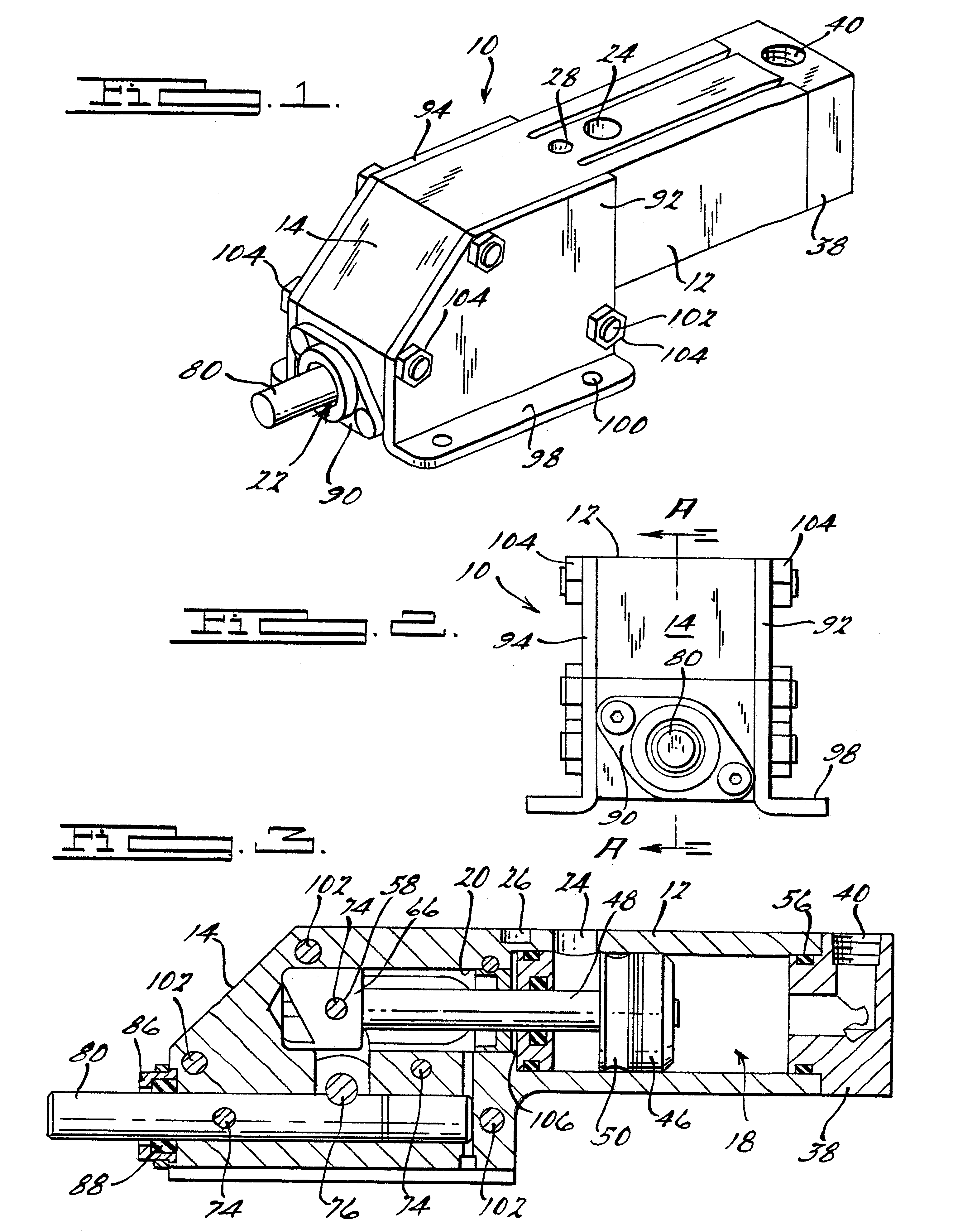
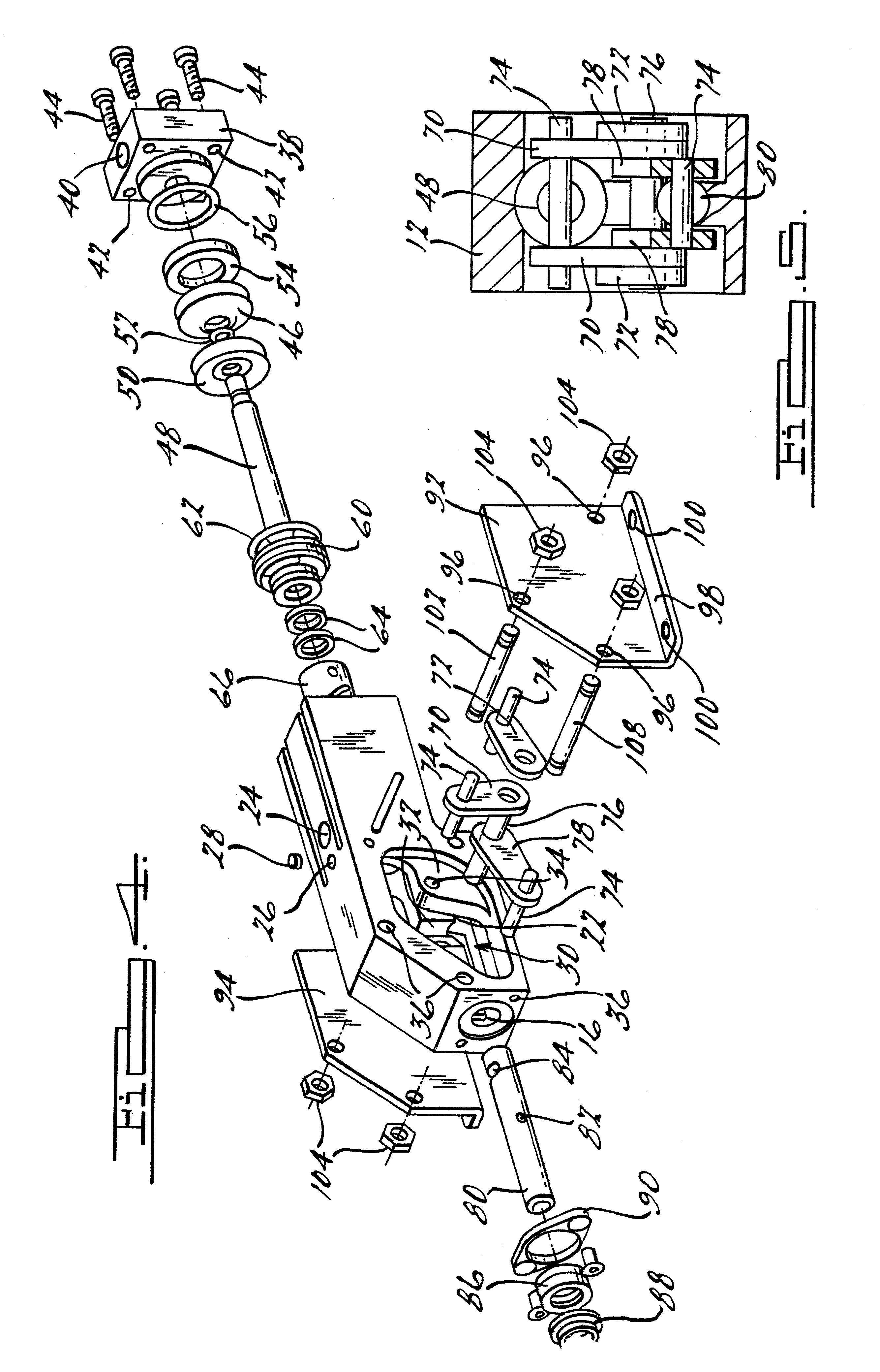
Referring to the drawings, a power clamp 10 according to the present invention is shown. It should be noted that the present invention shows a straight line action power clamp 10 but other types of power clamps may also utilize the innovations of the power clamp of the present invention. The power clamp 10 of the present invention generally is used in a manufacturing environment such as that of an automotive manufacturer or the like. In the manufacturing environment numerous robotic apparatuses including welding apparatuses are used near the clamps and weld slag from such devices has been known to contaminate prior art power clamps and reduce their reliability and effective life in the manufacturing environment.

FIGS. 1 through 5 show the power clamp 10 according to the present invention. The power clamp 10 includes a unitized body 12 that generally has a rectangular shape. One end of the body 12 has an angled surface 14 thereon. Directly below the angled surface 14 is an orifice 16...


PUM


Abstract

A power clamp for use in a manufacturing environment. The power clamp includes a unitized body having a bore in one end thereof The power clamp also includes a piston arranged within the bore and an end cap secured to the body on the end having the bore. The power clamp has a plurality of first links, one of the first links connected to the piston and at least one second link connected to the first link at a pivot point. A plunger is arranged within an orifice of the body and that plunger is connected to a second link. The power clamp also includes a plurality of identical pins with the pins connecting the links. The power clamp also includes a side plate connected to the body to enclose the clamp and protect it from the manufacturing environment.

Description

I. BACKGROUND OF THE INVENTION1. Field of the InventionThe present invention generally relates to clamps, and more particularly, relates to straight-line action pneumatic power clamps.2. Description of the Related ArtPower clamps have been known for many years in the prior art. There are numerous varieties of power clamps, such as hold down action power clamps, straight-line action power clamps, heavy-duty toggle clamps, etc. The power clamps generally are used for higher force applications, such as holding of automobile bodies during manufacturing thereof, securing large work pieces to work tables, securing large doors or other covers, such as those found on large trucks. Therefore, the durability and reliability of the clamp is important to the manufacturers who are forced to shut down manufacturing lines if a clamp fails.Many of the prior art power clamps include a cylinder connected to offset link arms. The offset link arms are attached to a base member. During operation of the ...

Claims


Application Information

Patent Timeline
Patent Type & Authority Patents(United States)
IPC IPC(8): B23Q3/08B25B5/00B25B5/12B66F7/00B66C1/00
CPCB25B5/122
Inventor RENTZ, MATTHEWDYKSTRA, HENRY
Owner DELAWARE CAPITAL FORMATION INC
Why Eureka
Try Eureka