Color temperature controlled and low THD LED lighting devices and systems and methods of driving the same

a led lighting and low thd technology, applied in the field of light emitting diodes, can solve the problems of operating costs, and increasing the cost of lighting devices. the effect of increasing the power factor and reducing the total harmonic distortion

Active Publication Date: 2016-01-26
LYNK LABS INC
View PDF66 Cites 55 Cited by
  • Summary
  • Abstract
  • Description
  • Claims
  • Application Information

AI Technical Summary

Benefits of technology

[0010]Accordingly, the present invention is provided to increase the performance of LED lighting devices driven by AC power. The LED lighting devices of the present invention seek to provide one or more of a color temperature controllable AC LED lighting device and / or an AC LED lighting device having an increased power factor and reduced total harmonic distortion.
[0035]According to one aspect of the invention a method of reducing total harmonic distortion in LED lighting circuits and devices is provided. The method requires that at least two LEDs be connected in series and that a bypass around or shunt at least one of the at least two LEDs connected in series is provided. A substantially constant current may be maintained flowing through at least one LED having while at least one LED is bypassed or shunted.

Problems solved by technology

However, LEDs powered by AC power sources act as a non-linear load.
As a result of the non-linearity, LEDs powered using AC power sources may have a lower power factor, and may have a greater total harmonic distortion, than existing halogen or incandescent lighting devices.
Having a low power factor and increased distortion may result in higher energy costs, transmission losses, and / or damage to electrical equipment.
In order to achieve this effect in LED lighting devices driven with AC power, complicated and expensive drive schemes are currently required which drive up the cost of the lighting device and the cost to operate the same.
However, the power supplies for this are very complex and larger in size.
Other complex versions of constant current or constant voltage DC with only two different LED colors can also be used, however these power supplies can also be large and complex.
These drive schemes may also be inefficient and waste additional power or electricity, further increasing operating costs.

Method used


Image

  • Color temperature controlled and low THD LED lighting devices and systems and methods of driving the same
  • Color temperature controlled and low THD LED lighting devices and systems and methods of driving the same
  • Color temperature controlled and low THD LED lighting devices and systems and methods of driving the same

Examples


Embodiment Construction

[0059]While this invention is susceptible to embodiments in many different forms, there is described in detail herein, various embodiments of the invention with the understanding that the present disclosures are to be considered as exemplifications of the principles of the invention and are not intended to limit the broad aspects of the invention to the embodiments illustrated.

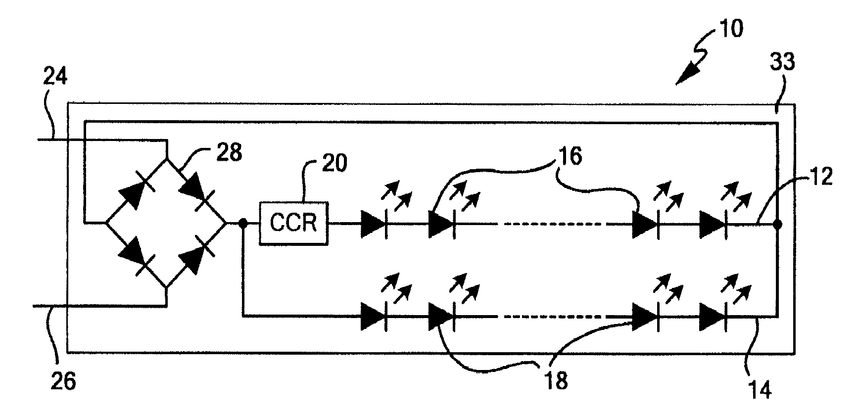
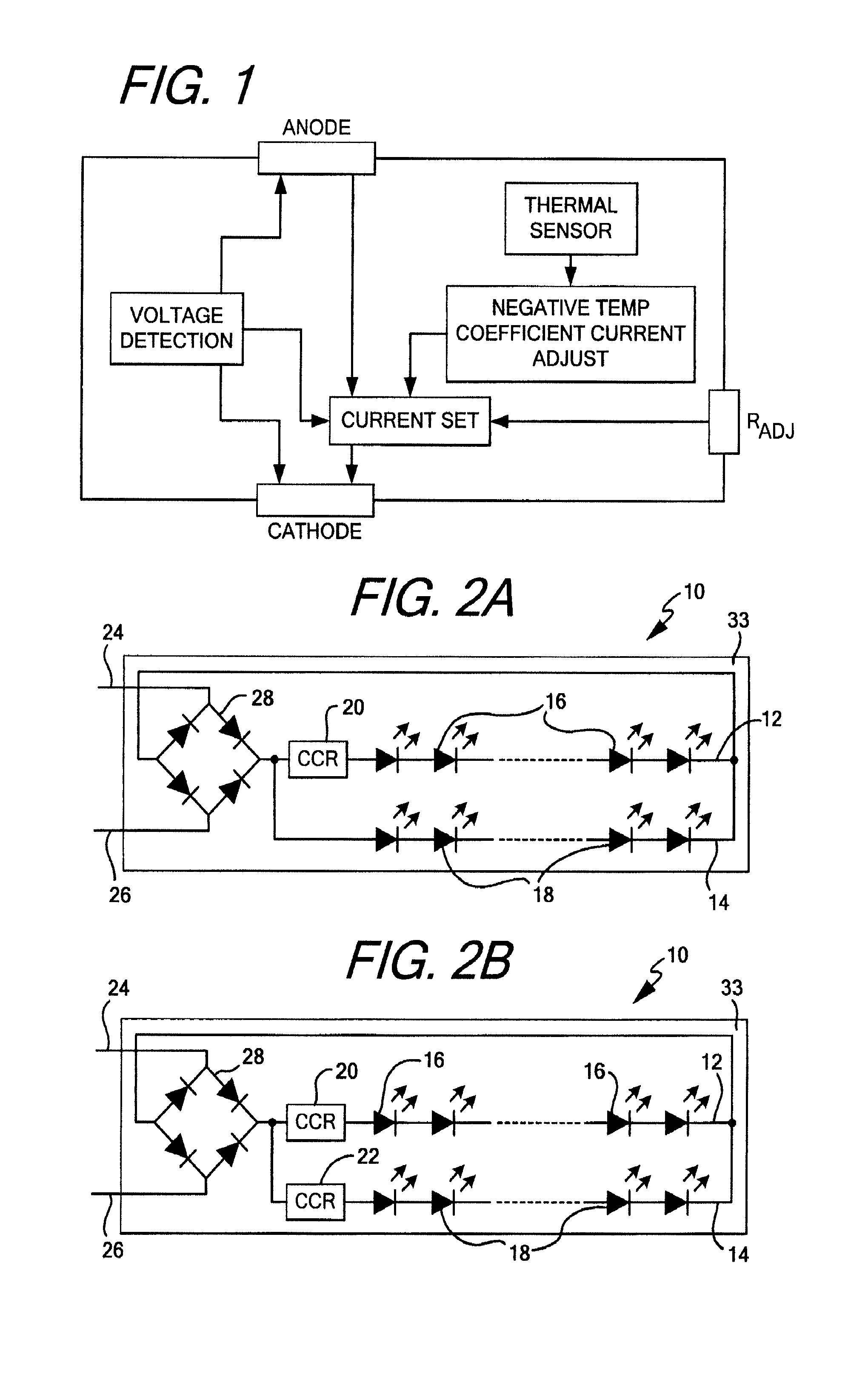
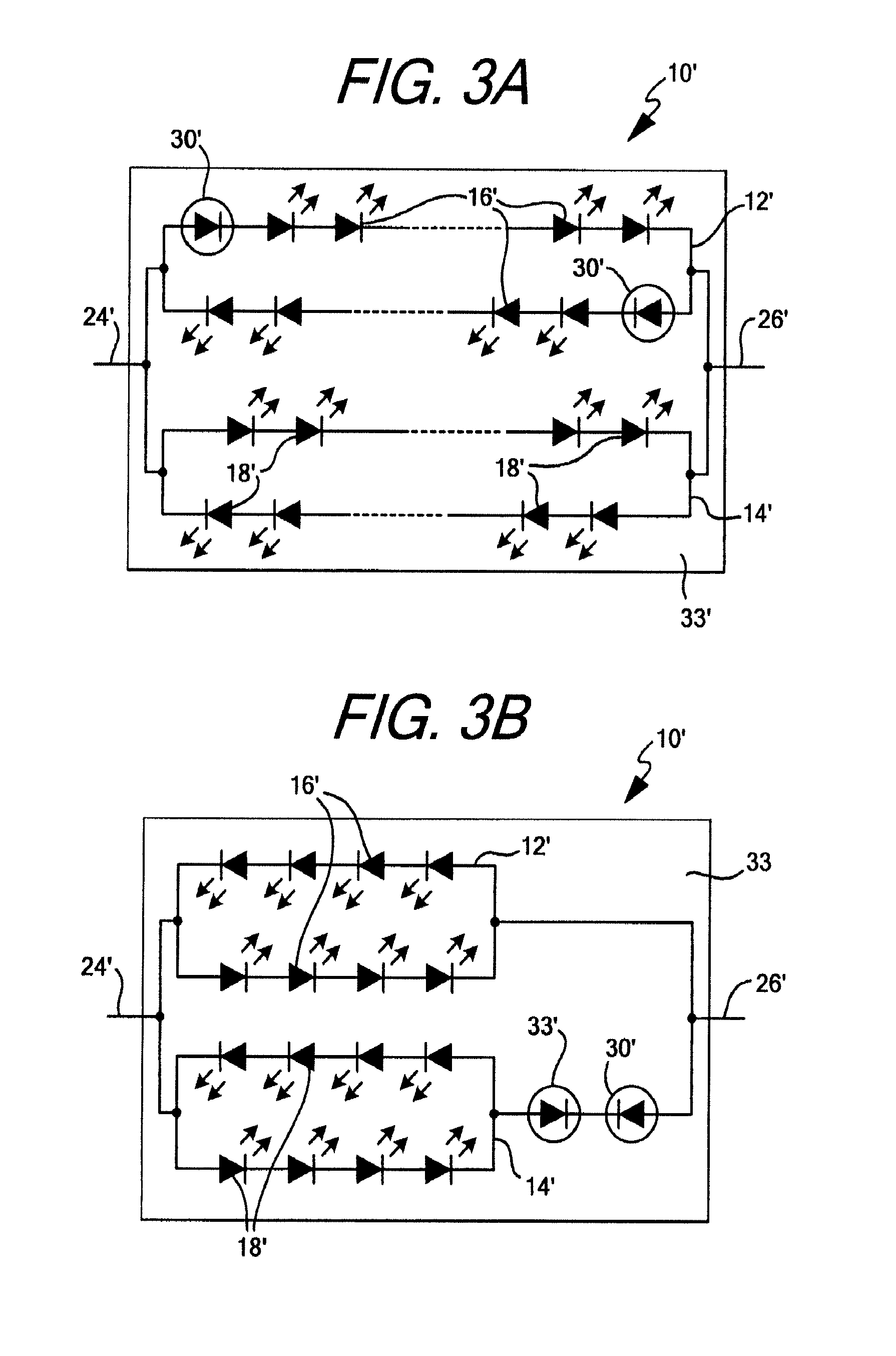
[0060]The present invention is directed to multiple lighting devices or systems, the light emitting circuits contained therein, and methods of driving and operating the same. As discussed herein, a lighting device may include any device capable of emitting light no matter the intention. Examples of lighting devices which are contemplated by this invention include, but are not limited to, LED chips, LED packages, LED chip on board assemblies, LED assemblies or LED modules. The devices may also include any required power connections or leads or contacts, or drivers, required to provide power to the circuits and ...


PUM


Abstract

The purposes of the devices described herein are to provide an LED lighting device capable of efficiently and economically emitting light having a selectable color temperature or a warm-on-dim feature when driven with AC power and to provide LED lighting devices which have an improved power factor and a reduced total harmonic distortion when powered with AC power.

Description

RELATED APPLICATIONS[0001]The present application is a 371 National Phase Application of PCT Application No. PCT / US2012 / 067623 entitled “Color Temperature Controlled and Low THD LED Lighting Devices and Systems and Methods of Driving the Same” filed Dec. 3, 2012, which claims priority to U.S. Provisional Application No. 61 / 630,025 entitled “Drive Method for Low THD and Color Temperature Changing LED Lighting Device Method and Apparatus” filed Dec. 2, 2011; U.S. Provisional Application No. 61 / 570,200 entitled “Drive Method for Low THD and Color Temperature Changing LED Lighting Device Method and Apparatus” filed Dec. 13, 2011; and, PCT Application No. PCT / US2012 / 051531 entitled “Devices and Systems Having LED Circuits and Methods of Driving the Same” filed Aug. 20, 2012—the contents of all of which are expressly incorporated herein by reference.TECHNICAL FIELD[0002]The present invention generally relates to light emitting diode (“LED”) circuits for use with AC voltage sources. More s...

Claims


Application Information

Patent Timeline
Patent Type & Authority Patents(United States)
IPC IPC(8): H05B41/16H05B33/08H05B44/00
CPCH05B33/083H05B33/0809H05B33/0821H05B33/0845H05B33/0857H05B33/0866H05B33/0872H05B45/20H05B45/24H05B45/42H05B45/397H05B45/44H05B45/46H05B45/48
Inventor MISKIN, MICHAELKOTTRITSCH, ROBERT L.
Owner LYNK LABS INC
Why Eureka
Try Eureka