
Heart-type circulation device

a circulation device and heart-type technology, applied in the direction of positive displacement liquid engine, heating type, lighting and heating apparatus, etc., can solve the problems of easy fire, serious affecting human health, electric leakage risk, etc., and achieve no noise, no leakage, and simple structure

Active Publication Date: 2016-02-09
ZHAO HENGLAI
View PDF5 Cites 0 Cited by
  • Summary
  • Abstract
  • Description
  • Claims
  • Application Information

AI Technical Summary

Benefits of technology

[0005]To overcome the above defects, the present invention provides a heart-type circulation device which has a simple structure, without an noise, and has no leakage and low repair rate, and is energy-saving and environment-friendly, green and efficient. The device is used in the pad which replaces the existing electric blanket and plumbing pad, that can provide comfort, health and safety for people.
[0008]The heart-type circulation device described by the present invention has a simple structure, which clever use the gravity of the liquid and the pressure of the self-pressing liquid storage tank, and combines with the check valve, the liquid cycle will be completed by just applying a minor power, the advantages are:1. It makes no noise. Because the present invention does not make the impeller rotate in high-speed, and does not have any parts with noise, thus it is quiet, green and efficient.2. It has no leakage and with low repair rate. The structure of the present invention leads to the seals thereof to wear small and difficult to generate a leakage.
[0009]It consumes less power, and it is energy-efficient. Most of the power consumed by the present invention is used to complete the liquid cycle, and the power for overcoming the resistance which is wasted is small, thus it has low loss and obtains high efficiency.
[0011]1. The self-pressing liquid storage tank of the present invention is made of rigid material, liquid is not filled up with therein, the space above the liquid surface is air; or the self-pressing liquid storage tank is made of elasticity material, liquid is filled up with therein. In this manner, when the liquid in the pipeline is pressed into the self-pressing liquid storage tank, the air or the elasticity material of the self-pressing liquid storage tank is extruded, the liquid flowed into the self-pressing liquid storage tank will be suffered pressure of it, and coordinated with other components of the device to complete the whole liquid cycle.2. The present invention further comprises a heating pipe which is connected with the pipeline. Because the role of the heating pipe, the temperature of the liquid in the pipeline will be elevated, and it has an advantage of comfortable and healthy to dispose the pipeline on the pad, it can prevent the leakage, and obtains higher safety.3. The cover plate of the present invention is made of magnetic material, the power system comprises a core, a coil, an insulation plate and a pulse power, in which the coil is wound on the core, the both end of the coil are connected with the pulse power, and the insulation plate is disposed on the top of the core. The above structure uses the pulse power which makes the devise has not always been energized, this is enough for the plumbing heating pad, thus it consumes less power and is energy-efficient.
[0014]The frequency of the pulse power is adjustable. When the frequency is increased, the cycle speed of the liquid in the pipeline is accelerated.
[0017]5. A concave platform is disposed on the periphery of the core of the power system, the concave platform is adapted to the pressing compact ring; the power system further comprises several limit stops, the section of the limit stop is groove profile, the cover plate and the concave platform are clipped in the groove, the bottom of the limit stop is fixed on the underside of the concave platform, the top of the aid limit stops are provided with adjustment screws. The distance of the cover plate can be adjusted by the adjusting screws, thereby a comfortable distance can be maintained between the cover plate and the top surface of the core to ensure the elastic plate and the cover plate can be fitted and separated from each other.6. The depth of the concave platform of the core is less than the thickness of the pressing compact ring. In this manner, when the cover plate is fitted with the elastic plate, the pressure of the whole cover plate is undertaken by the concave platform, thereby the abrasion of the elastic plate from the core or the insulation plate is reduced.7. The present invention further comprises several springs which are disposed between the concave platform and the pressing compact ring. When the electric current of the coil is equaled to zero, the pressure suffered by the pressing plate is removed, the spring which was under the compress state starts to stretch, the cover plate moves upward, and the water will continually flow into the reservoir space with the movement of the cover plate. In this manner, in the case of not need to generate a higher pressure, can be, the liquid can continually flow into the water inlet via the check valve A depending on its gravity, so the reservoir space of the self-pressing liquid storage tank is formed more easily.8. The power system further is consisted of a cam mechanism or cylinder mechanism. The elastic plate is extruded by the unique motion of the cam or the repeated motion of the cylinder, thereby the fit and separation of the elastic plate and the cover plate can be obtained.9. The check valve A and the check valve B are mechanical valves or solenoid valves.

Problems solved by technology

However, its disadvantage is also obviously, a large number of the resistance wires inside of the electric blanket generate high electromagnetic radiation, which could affect the human health seriously.
In addition, the electric blanket further makes the people feel dry easily, and has electric leak risk, and results the fire easily if it has been electrified for a long time.
1. It has loud noise. When the blade is rotating, it will generate a loud noise which will affect the people's sleeping.
2. It usually has leakage and high repair rate. Because the blade always has been kept rotating in the rotate state, thus the seal of the blade can be damaged by attrition easily, the leaked water would soak the pads and clothing, which might cause a great inconvenience to usage.
3. It consumes high energy. Because the motor always drive the blade to rotate, thus it will always consume energy when it is turned on by a long time for warm, the energy saving performance is poor.

Method used


Image

  • Heart-type circulation device
  • Heart-type circulation device
  • Heart-type circulation device

Examples


Embodiment Construction

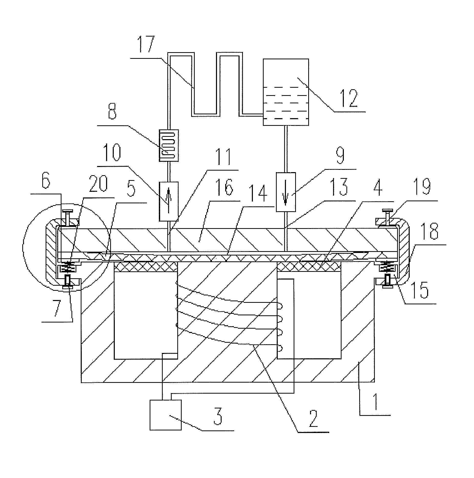
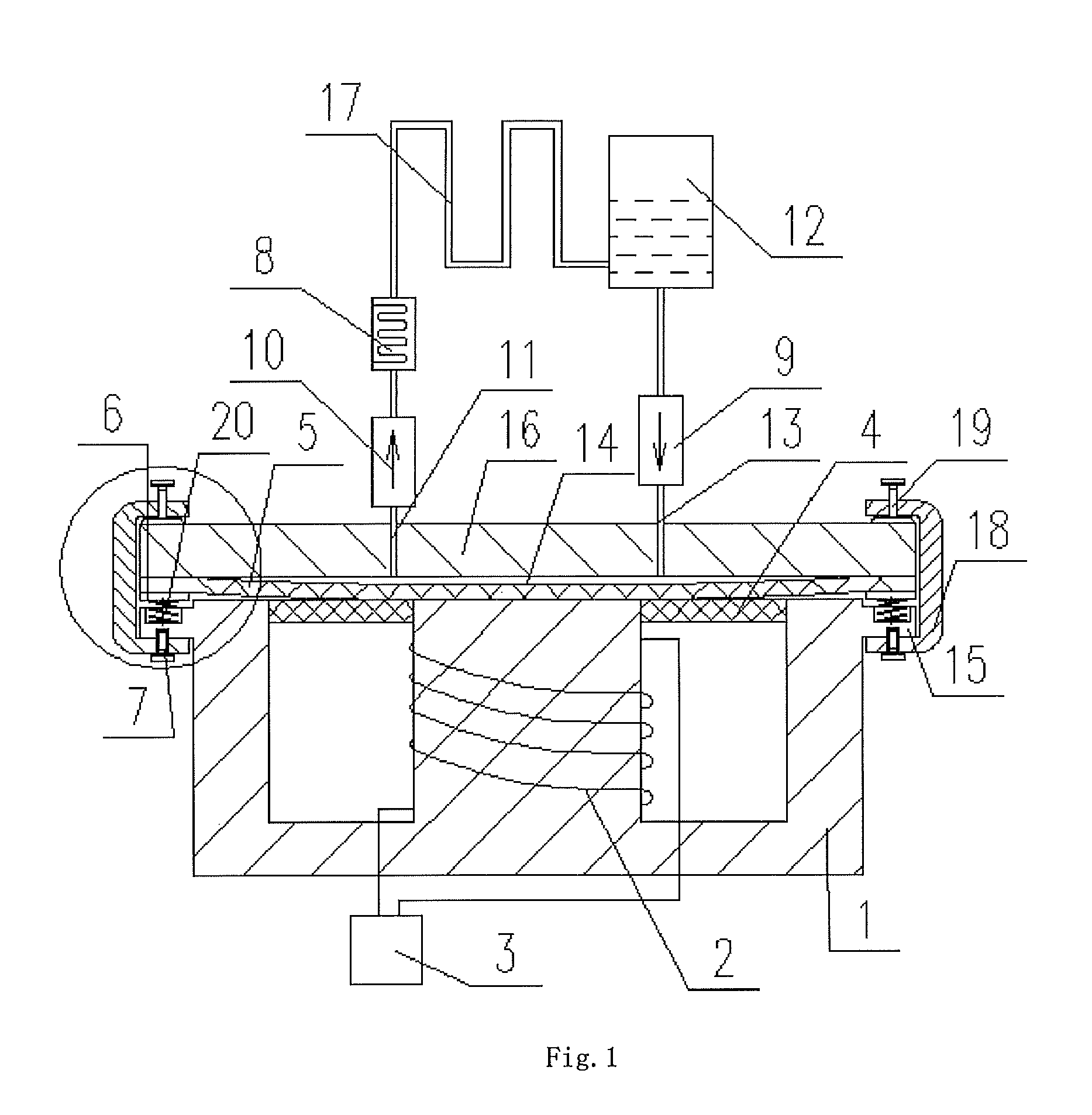
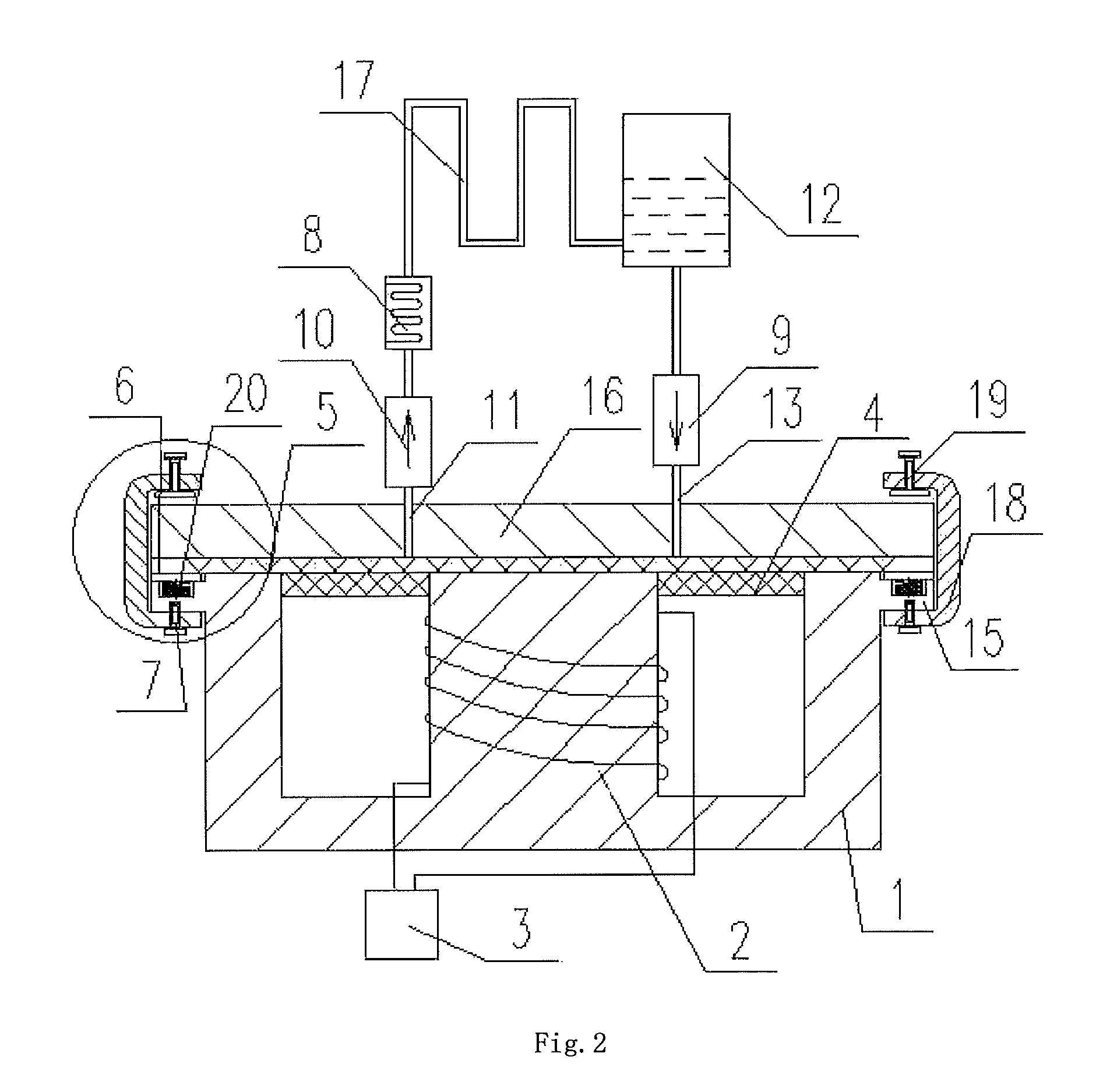
[0027]Hereafter, the heart-type circulation device of the present invention will be described in detail by referring to FIGS. 1-4.

[0028]The heart-type circulation device of the present invention comprises a circulation system and a power system.

[0029]As shown in FIGS. 3 and 4, the circulation system stores water in the internal, including a cover plate 16, an elastic plate 5, a pressing compact ring 6, a water inlet 13, a check valve A 9, a self-pressing liquid storage tank 12, a check valve B 10, a water outlet 11, a pipeline 17 and a screw 7.

[0030]The cover plate 16 is an iron product, the cover plate 16 and the elastic plate 5 are both in round shape, they are tightly fixedly connected at the entire edge of the circumference, the connection is that the pressing compact ring 6 is disposed on one side of the elastic plate 5 which is away from the cover plate 16, the pressing compact ring 6 and the elastic plate 16 and cover plate 16 are fixedly connected by the screw 7, as shown in...


PUM


Abstract

A heart-type circulation device comprises a power system, a cover plate (16), an elastic plate (5), a pressing contact ring (6), a water inlet (13), a check valve A (9), a self-pressing liquid storage tank (12), a check valve B (10), a water outlet (11), and a pipeline (17). The elastic plate (5) is disposed above the power system, the pressing contact ring (6) is disposed on the periphery of a bottom surface of the elastic plate (5), and the pressing contact ring (6), the elastic plate (5), and the cover plate (16) are fixedly connected in sequence from bottom to top. The water inlet (13) and the water outlet (11) are in communication with each other between the cover plate (16) and the elastic plate (5) via the cover plate (16) respectively. The water inlet (13), the check valve A (9), the self-pressing liquid storage tank (12), the check valve B (10), and the water outlet (11) are connected in sequence via the pipeline (17), wherein the direction of the check valve A (9) is the direction of a fluid flowing to the cover plate (16), and the direction of the check valve B (10) is the direction of the fluid flowing out of the cover plate (16). The space where the whole pipeline (17) is in communication with the self-pressing liquid storage tank (12) is filled up with a liquid. The heart-type circulation device has a simple structure, makes no noise, and has no leakage and a low maintenance rate, and is energy-saving, environment-friendly, green and efficient.

Description

FIELD OF THE INVENTION[0001]The present invention relates to a new circulation device, specifically relates to a heart-type circulation device.BACKGROUND OF THE INVENTION[0002]Electric blanket used daily is provided with resistance wire which is distributed in the inside of the blanket uniformly, and generates heat by heating the resistance wire. However, its disadvantage is also obviously, a large number of the resistance wires inside of the electric blanket generate high electromagnetic radiation, which could affect the human health seriously. In addition, the electric blanket further makes the people feel dry easily, and has electric leak risk, and results the fire easily if it has been electrified for a long time.[0003]Even if with a circulation plumbing pad, the existing circulation device also uses the centrifugal pump mainly, that is, an impeller is driven by a pump shaft to rotate, that has an action on the fluid between the blades, and the fluid is thrown to the periphery o...

Claims


Application Information

Patent Timeline
Patent Type & Authority Patents(United States)
IPC IPC(8): E03B7/07A47C21/04F24H1/10F24H9/14F04B17/04F04B23/02F04B43/04A61F7/00A47G9/02
CPCA61F7/0097A47C21/048A47G9/0215F04B17/04F04B23/02F04B43/04F24H1/101F24H9/14A61F2007/0054F24H2250/08Y10T137/6606A47C21/04F24D3/02F24D19/08
Inventor ZHAO, HENGLAI
Owner ZHAO HENGLAI
Learn More