
Variable placement hinge for agricultural implement to maintain constant work zone spacing

a technology of agricultural implements and hinges, which is applied in the field of agricultural implements, can solve the problems of flexing of implements, causing spacing inconsistencies, and affecting so as to achieve the effect of ensuring the spacing between the two sides of the joint, and ensuring the stability of the join

Active Publication Date: 2016-02-16
BLUE LEAF I P INC
View PDF14 Cites 9 Cited by
  • Summary
  • Abstract
  • Description
  • Claims
  • Application Information

AI Technical Summary

Benefits of technology

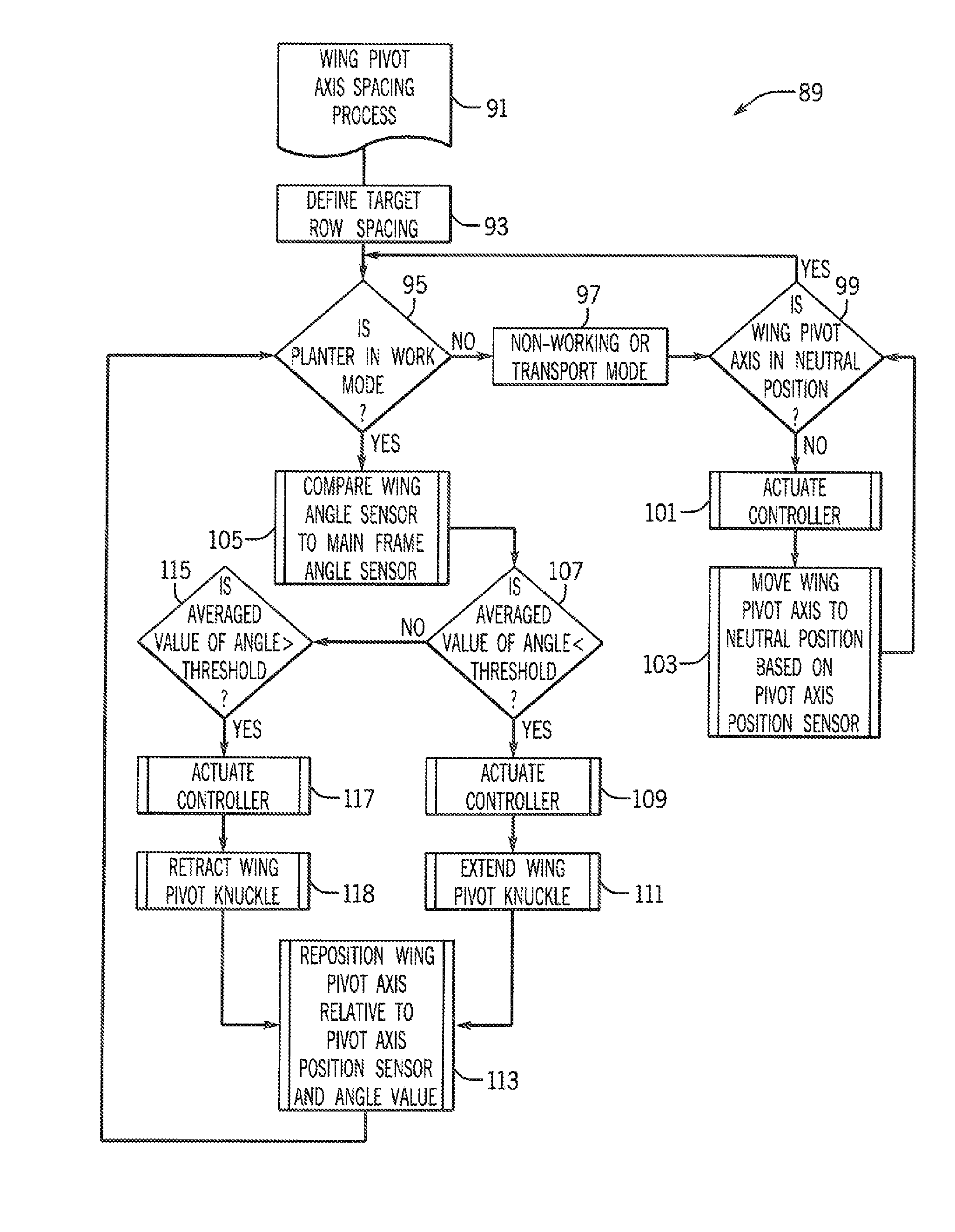
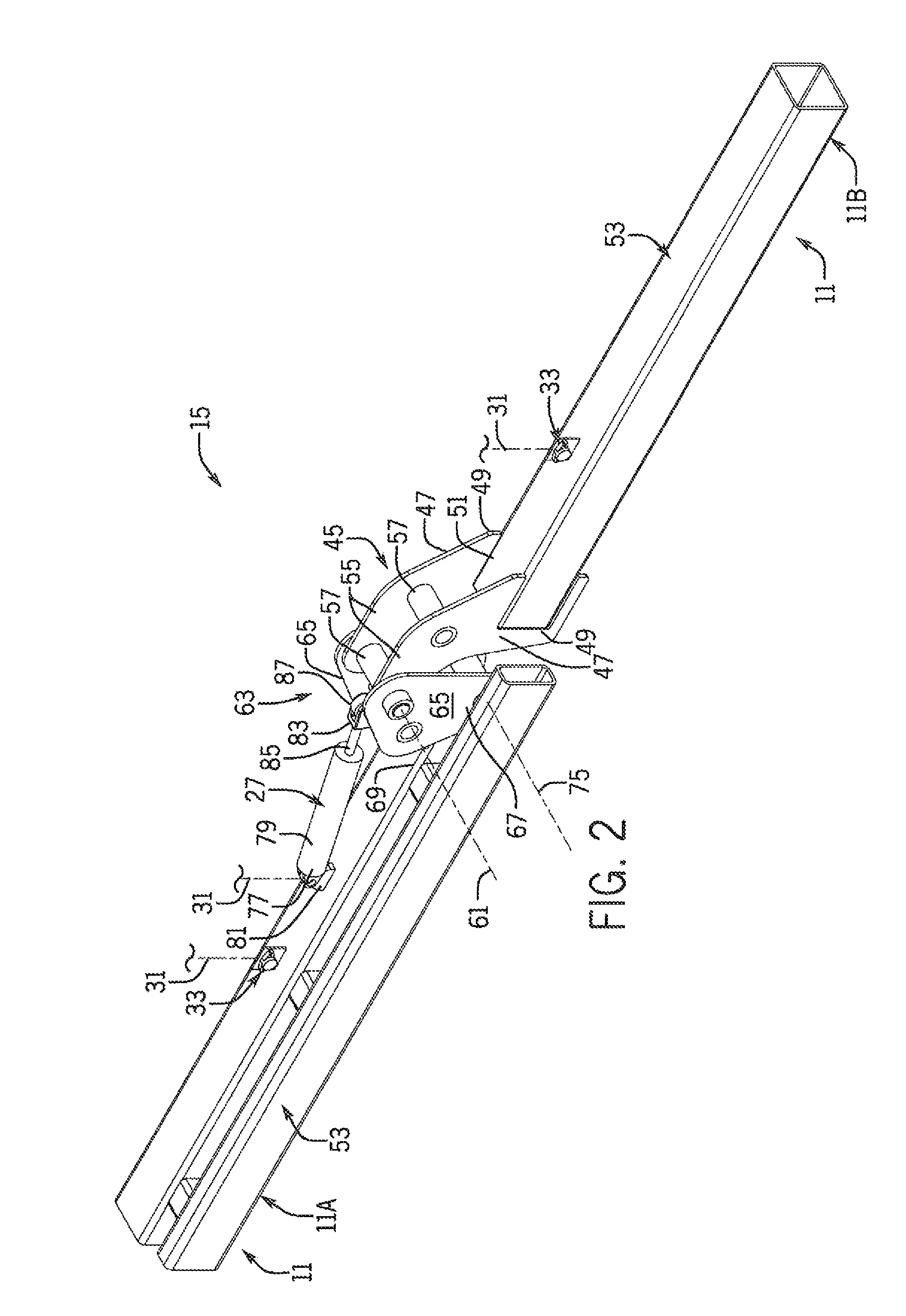
The invention relates to an agricultural implement with variable spacing between work zones. The implement includes two sections: a first section covering a first part of the field and a second section covering a second part of the field. The sections are connected by a hinge joint that allows flexing of the implement for uneven terrain. A pivot knuckle is movable to adjust the spacing between the work zones. An angle sensor detects the deviation of the second section from a reference position and a controller controls the actuator to move the pivot knuckle accordingly. The amount of pivot knuckle travel is a function of the angular deviation and the position of the pivot knuckle, which ensures a compact design of a variable position hinge joint. The technical effect is the ability to adjust the spacing width boundary between the adjacent implement sections based on the amount of deviation of the second section from a reference position.

Problems solved by technology

When the implement sections move closer to each other, a pair of ground-engaging tools or other working units closest to and on opposite sides of the joint can potentially collide with each other.
This can limit will flex due to the ground-engaging equipment hitting each other.
In this way, despite using precision agricultural guidance systems, the implement flexing can create spacing inconsistencies between planted rows or areas in the field at boundaries between adjacent work zones that are worked by adjacent implement sections.
Spacing inconsistencies can reduce the accuracy of subsequent product application or harvesting from non-matching precision product placement row equipment.

Method used


Image

  • Variable placement hinge for agricultural implement to maintain constant work zone spacing
  • Variable placement hinge for agricultural implement to maintain constant work zone spacing
  • Variable placement hinge for agricultural implement to maintain constant work zone spacing

Examples


Embodiment Construction

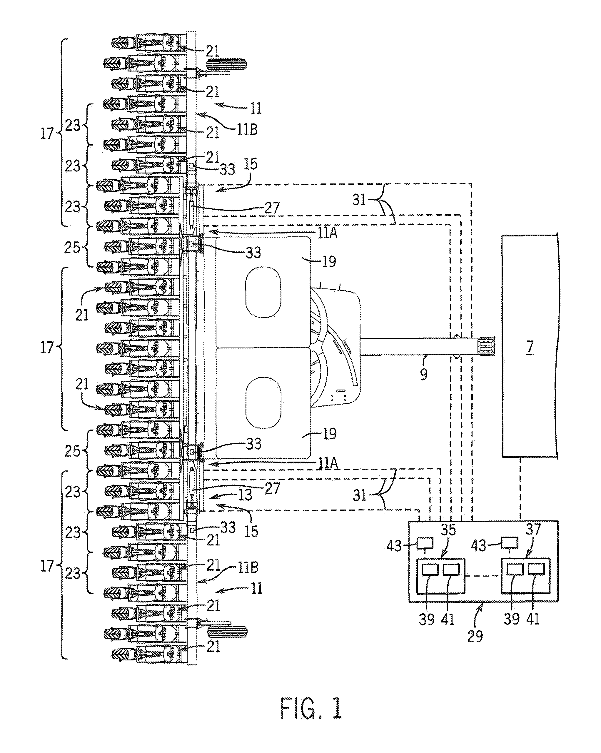
[0021]Referring now to the drawings and specifically to FIG. 1, an agricultural implement 5 is shown towed behind a tractor 7, shown in schematic form, by way of a drawpole 9 that is aligned with a centerline or longitudinal axis of the implement 5. Implement sections 11 are connected to each other through a variable work zone spacing system 13. The variable work zone spacing system 13 includes variable placement hinge joint assemblies 15 interconnecting adjacent implement sections 11. The hinge joint assemblies 15 allow the implement 5 to flex by passively allowing the implement sections 11 to pivot with respect to each other for accommodating uneven terrain of the agricultural field and are configured to adjust spacing between adjacent works zones 17 defined by portions of respective implement sections 11, as described in greater detail elsewhere herein. Implement 5 is shown here as a bulk fill planter with toolbar sections or boom sections that define the implement sections 11. T...


PUM


Abstract

An agricultural implement is provided that has a variable placement hinge joint that allows adjacent implement sections to flex relative to each other and can be moved by an actuator to control spacing between adjacent work zones defined by the implement sections. This can be done by detecting relative angle changes between adjacent implement sections and moving the hinge joint to maintain a constant distance between the work zones so that row spacing is substantially constant across the entire implement, even between adjacent ground-engaging tools or other working units of different implement sections.

Description

FIELD OF THE INVENTION[0001]The subject matter disclosed herein relates generally to the agricultural implements and, in particular, to implements with folding or rotating flame sections that allow for transporting the implements on the road in relatively compact configurations and sections or segments having independent ground-following capabilities when in work positions.BACKGROUND OF THE INVENTION[0002]Modern farming practices strive to minimize operating expenses. One way of reducing operating expenses is to increase the size of planting and seeding implements so as to reduce the amount of tractor operational time required for planting or seeding. Large planting and seeding implements may include multiple implement sections such as boom sections, toolbar sections, and / or wing sections that are hinged to each other at joints, typically single fixed joints, to allow the implement to flex by pivoting at the joints to accommodate uneven terrain in agricultural fields. Downward flexi...

Claims


Application Information

Patent Timeline
Patent Type & Authority Patents(United States)
IPC IPC(8): G06F7/70G06F19/00G06G7/00G06G7/76A01C7/20
CPCA01C7/201A01B63/32A01B73/04A01C7/208A01B73/044
Inventor PRICKEL, MARVIN A.CONNORS, MICHAEL J.
Owner BLUE LEAF I P INC
Learn More