Exhaust system conduit with thermal/noise insulation

a technology of exhaust system and conduit, applied in the direction of sleeve/socket joint, mechanical equipment, machine/engine, etc., can solve the problems of undue heat stress, vibration and other movement, and the prior art exhaust system of this type is not completely free of problems, so as to reduce vibration, resist heat transmission, and suppress noise transmission

Active Publication Date: 2016-02-16
TRU FLEX
View PDF20 Cites 4 Cited by
  • Summary
  • Abstract
  • Description
  • Claims
  • Application Information

AI Technical Summary

Benefits of technology

[0007]The insulation layer may be constructed of any suitable material that is effective to suppress noise transmission within the conduit and to resist heat transmission. Additionally, the insulation provides a barrier that dampens vibration and prevents the inside and outside layers of the pipe from physically contacting each other. As a consequence, the conduit and the joints it makes with other pipe exhibit improved noise control, reduced heat transmission, diminished vibration, and enhanced structural capabilities. The conduit provides particular utility as a joint between two other pipes, and the joint may be constructed as either a torsional joint or a non-torsional joint depending upon the application.

Problems solved by technology

Even so, the prior art exhaust systems of this type have not been completely free of problems.
In particular, the vibration and other movement creates substantial noise which can be aggravated by the hot exhaust gases going through the pipes.
Additionally, the heat from the exhaust gases causes the outside surfaces of the pipes to reach temperatures that can be high enough to create undue heat stress on the piping and safety hazards if contacted by persons.
These noise and heat problems have not been successfully addressed and have been increasing causes for concern due to the increasing emphasis that has been placed on controlling noise pollution and increasing concern with safety considerations.

Method used


Image

  • Exhaust system conduit with thermal/noise insulation
  • Exhaust system conduit with thermal/noise insulation
  • Exhaust system conduit with thermal/noise insulation

Examples


Embodiment Construction

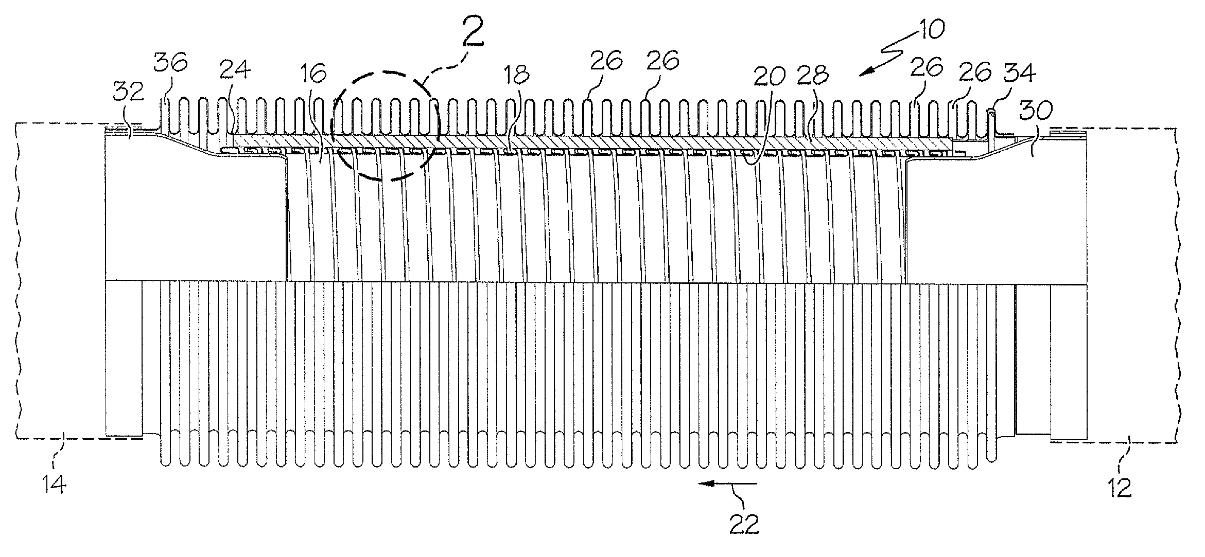
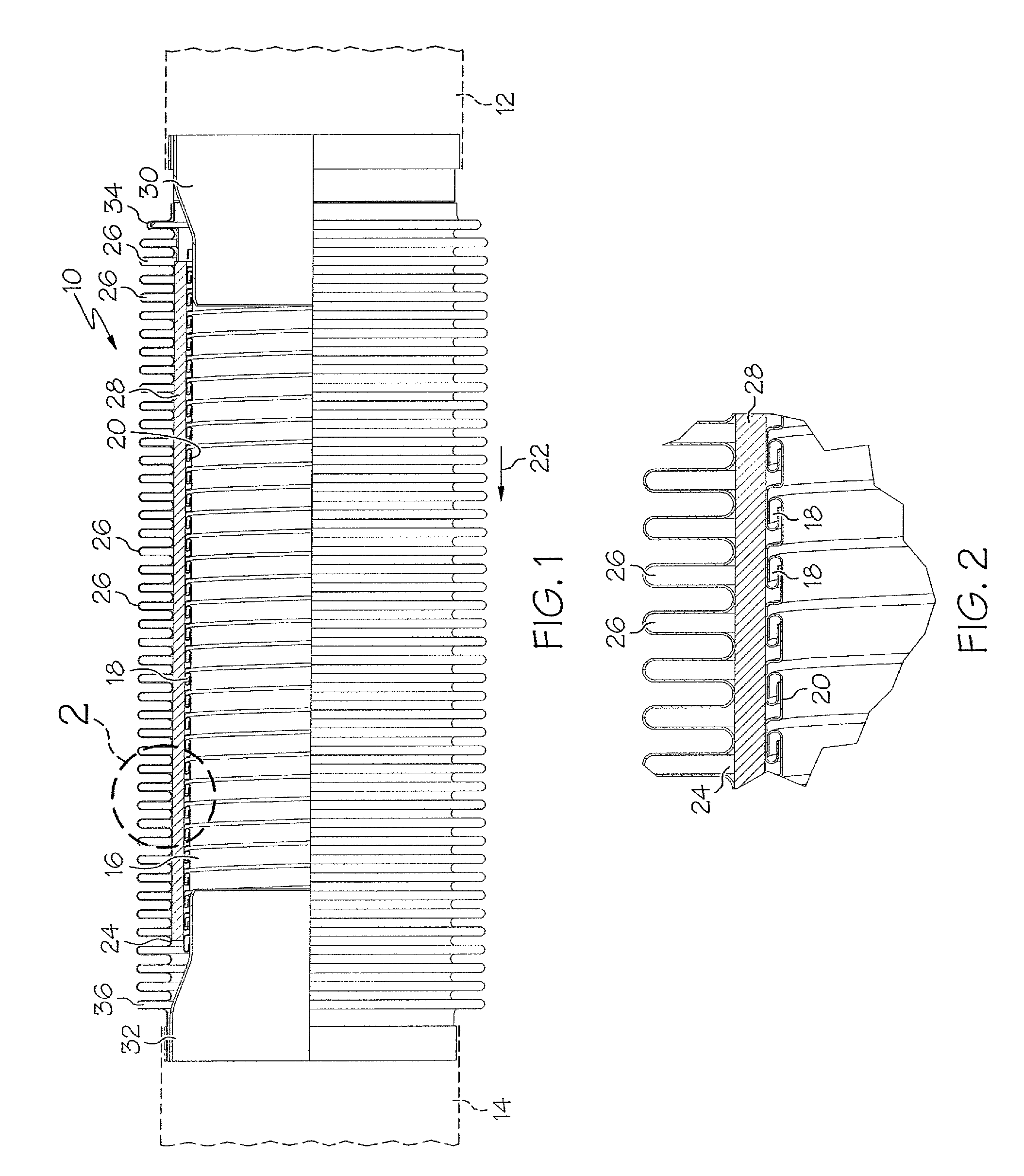
[0014]Referring now to the drawings in more detail and initially to FIG. 1, numeral 10 generally designates a conduit which is constructed according to one embodiment of the present invention. The conduit 10 may couple together a pair of pipes 12 and 14. By way of example, the conduit 10 and the pipes 12 and 14 may be parts of a vehicular exhaust system through which exhaust gases flow.

[0015]The conduit 10 has an inner cylindrical liner portion 16 which may be constructed as a flexible conduit formed by a spirally wound strip 18 having edges of adjacent windings interlocked in the manner described in U.S. Pat. No. 6,427,727 to Thomas which is incorporated by reference. The liner portion 16 has a flexible construction which allows it to flex in a manner to withstand the forces that are applied to it in service. The liner portion 16 provides a cylindrical bore 20 through which the hot vehicular exhaust gases pass from pipe 12 to pipe 14, as shown by the directional arrow 22 in FIG. 1....


PUM


Abstract

A flexible conduit for use in a pipe system such as a vehicular exhaust system to provide a torsional or non-torsional joint between two pipes. The conduit has an outer bellows and an inner liner between which a layer of noise / thermal insulation is sandwiched.

Description

CROSS-REFERENCE TO RELATED APPLICATIONS[0001]None.FIELD OF THE INVENTION[0002]This invention relates generally to the field of pipe systems and more particularly to a flexible pipe system such as the type commonly used in vehicular exhaust systems or farm equipment, construction equipment, or other equipment.BACKGROUND OF THE INVENTION[0003]Flexible pipe and conduit structures are used in a variety of applications. For example, vehicular exhaust systems make use of flexible conduits in order to accommodate the jarring, vibration and thermal stresses to which the exhaust system is subjected when the vehicle is in use. Examples of spiral wound flexible pipes suitable for use in vehicular exhaust systems are disclosed in U.S. Pat. No. 6,497,254 to Thomas et al. Bellows type systems which provide flexibility by using corrugated conduits are exemplified by U.S. Pat. No. 7,066,495 to Thomas et al. The latter patent also discloses an arrangement for interfitting the corrugations on the pip...

Claims


Application Information

Patent Timeline
Patent Type & Authority Patents(United States)
IPC IPC(8): F16L11/15F16L11/26F01N13/14F16L51/02F16L55/033
CPCF16L51/026F01N13/143F01N13/148F16L11/26F16L55/0336F01N2470/12F16L11/12
Inventor STALCUP, II, ROBERT F.SWANK, SCOTT R.THOMAS, R. WINFIELD
Owner TRU FLEX
Why Eureka
Try Eureka