Structured RF coil assembly for MRI scanner

a technology of mri scanner and rf coil, which is applied in the field of magnetic resonance imaging, can solve problems such as mutual annihilation

Active Publication Date: 2016-02-16
GENERAL ELECTRIC CO
View PDF16 Cites 35 Cited by
  • Summary
  • Abstract
  • Description
  • Claims
  • Application Information

AI Technical Summary

Problems solved by technology

As these positrons travel through the tissues of the subject, they lose kinetic energy and ultimately collide with an electron, resulting in mutual annihilation.
However, in a conventional MRI scanner, the RF shield is cylindrical and resides on the inner diameter of the gradient coil and hence there is no space for such a PET detector array.

Method used


Image

  • Structured RF coil assembly for MRI scanner
  • Structured RF coil assembly for MRI scanner
  • Structured RF coil assembly for MRI scanner

Examples


Embodiment Construction

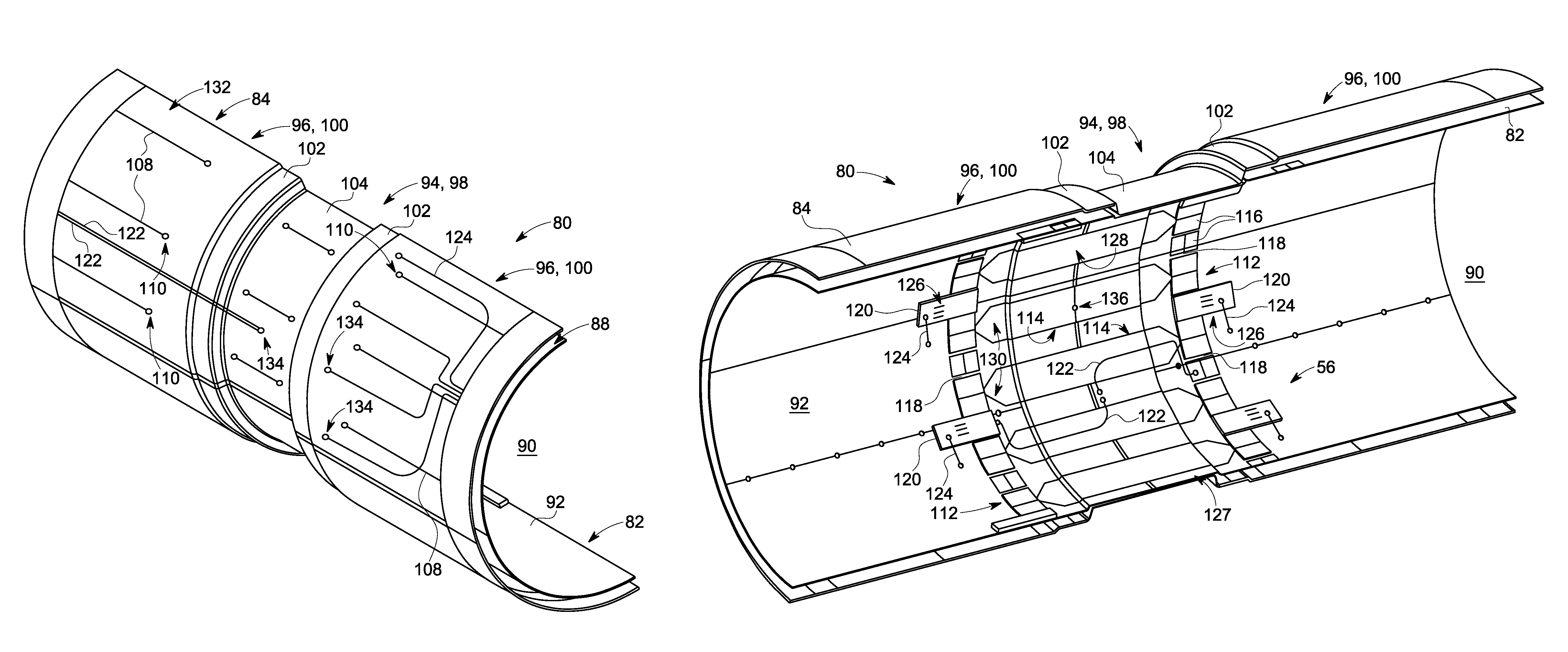
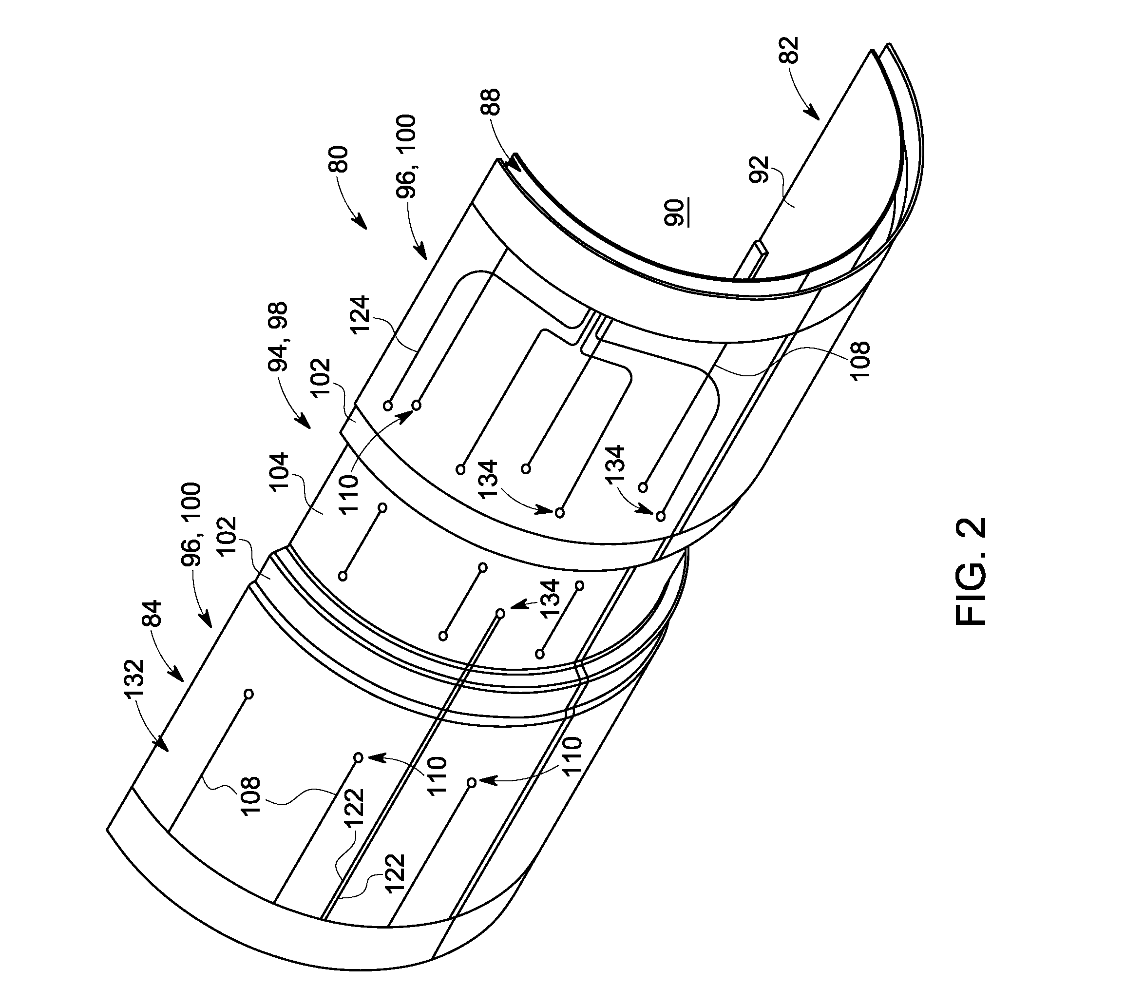
[0018]An RF coil assembly is provided that includes an RF shield having an indentation formed therein in a region thereof. An RF coil in the RF coil assembly is shaped to conform to the shape of the RF shield so as to increase the efficiency of the RF coil and reduce the local specific absorption rate (SAR) experienced by a patient.

[0019]According to embodiments of the invention, the RF coil assembly can be implemented in a variety of imaging systems or apparatuses. For example, the RF coil assembly can be incorporated into a stand-alone MR imaging system or can be incorporated into a hybrid MR imaging system, such as a hybrid PET-MR imaging system, for example. Thus, while embodiments of the invention are set forth here below with respect to a hybrid PET-MR imaging system, it is recognized that other stand-alone and hybrid MR imaging systems are considered to be within the scope of the invention.

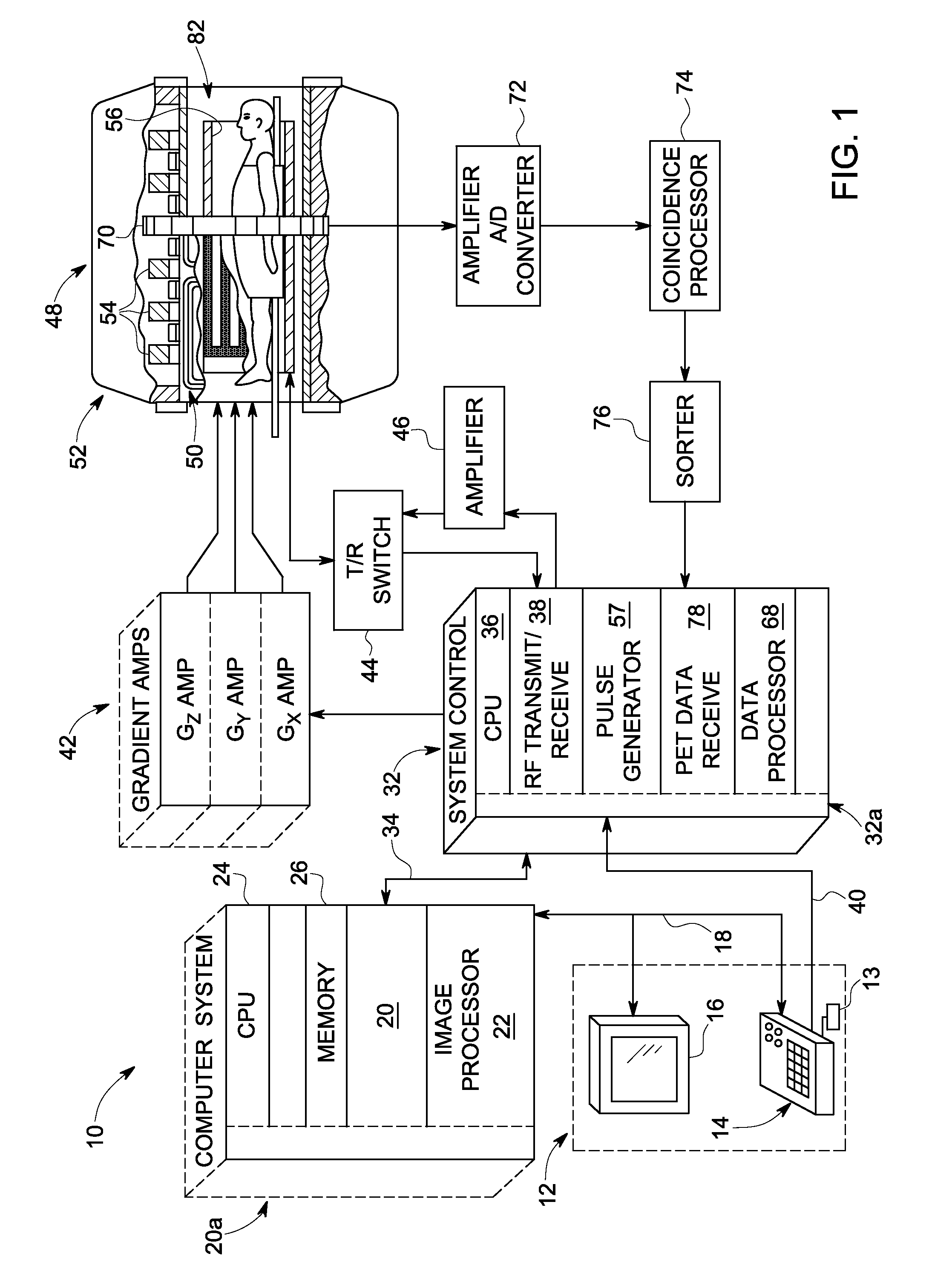
[0020]Referring to FIG. 1, the major components of an exemplary hybrid PET-MR imaging s...


PUM


Abstract

An imaging apparatus that incorporates an RF coil assembly and RF shield as part of a magnetic resonance imaging (MRI) system is disclosed. The imaging apparatus includes an MRI system having a plurality of gradient coils, an RF coil former having inner and outer surfaces, an RF shield positioned on the outer surface of the RF coil former so as to be formed about the RF coil former, and an RF coil positioned on the inner surface of the RF coil former, with the RF coil coupled to a pulse generator to emit an RF pulse sequence and receive resulting MR signals from a subject of interest. The RF coil former comprises a generally cylindrical member having an indented portion indented in a radial direction inwardly from the outer surface, with the RF shield conforming to the RF coil former so as to also have an indented portion.

Description

BACKGROUND OF THE INVENTION[0001]Embodiments of the invention relate generally to magnetic resonance (MR) imaging, and more specifically, to an RF coil assembly and RF shield configured to accommodate positioning of elements therein, such as a positron emission tomography (PET) detector array for use in a hybrid PET-MRI system.[0002]PET imaging involves the creation of tomographic images of positron emitting radionuclides in a subject of interest. A radionuclide-labeled agent is administered to a subject positioned within a detector ring. As the radionuclides decay, positively charged particles known as “positrons” are emitted therefrom. As these positrons travel through the tissues of the subject, they lose kinetic energy and ultimately collide with an electron, resulting in mutual annihilation. The positron annihilation results in a pair of oppositely-directed gamma rays being emitted at approximately 511 keV.[0003]It is these gamma rays that are detected by the scintillators of t...

Claims


Application Information

Patent Timeline
Patent Type & Authority Patents(United States)
IPC IPC(8): G01R33/48G01R33/422G01R33/34A61B6/00A61B6/03A61B5/00A61B5/055
CPCG01R33/481A61B5/0035A61B6/037A61B6/4258A61B6/4417G01R33/34076G01R33/422A61B5/055
Inventor BOSKAMP, EDDY BENJAMINMCKINNON, GRAEME C.AMJAD, ARSLAN
Owner GENERAL ELECTRIC CO
Why Eureka
Try Eureka