Pressure balance valve

a pressure balance valve and valve body technology, applied in the direction of ratio control, thin material processing, instruments, etc., can solve the problems of high machining cost, inability to precisely adjust the desired mixing ratio of cold water and hot water, etc., to achieve excellent pressure balance, improve tolerance of the present invention, and reduce manufacturing cost

Inactive Publication Date: 2016-02-16
GLOBE UNION INDAL
View PDF11 Cites 1 Cited by
  • Summary
  • Abstract
  • Description
  • Claims
  • Application Information

AI Technical Summary

Benefits of technology

[0010]The primary object of the present invention is to provide a pressure balance valve which is capable of overcoming the shortcomings of the conventional pressure balance valve.
[0017]Thereby, a tolerance among the inner wall of the receiving chamber, the outer wall of the first ring portion, and the outer wall of the second ring portion can be increased, i.e., the tolerance of the present invention is increased to 0.2 mm, but a conventional tolerance is limited less than 0.03 mm, and 0.03 mm<D2−D1<0.2 mm or 0.1 mm<D2−D1<0.2 mm preferably. In other words, the tolerance of the present invention is increased, but the pressure balance valve still has excellent pressure balance. Accordingly, two size precisions of an outer diameter of an outer wall of the valve core and the inner diameter of the inner wall of the receiving chamber are greatly reduced, thus lowering manufacturing cost.
[0019]In addition, a surface roughness of the valve core is reduced greatly so as to eliminate surface grinding process, thus saving machining cost.

Problems solved by technology

However, when the cold-water pressure of the cold-water orifice and the hot-water pressure of the hot-water orifice are not equal, the desired mixing ratio of the cold water and the hot water cannot be adjusted precisely.
To comply with above-mentioned requirements, a gap between an outer surface of the valve core and an inner surface of the housing has to be less than 0.03 mm, and the outer surface of the valve core and the inner surface of the housing have to be machined smoothly, thus causing high machining cost.

Method used


Image

  • Pressure balance valve
  • Pressure balance valve
  • Pressure balance valve

Examples


Embodiment Construction

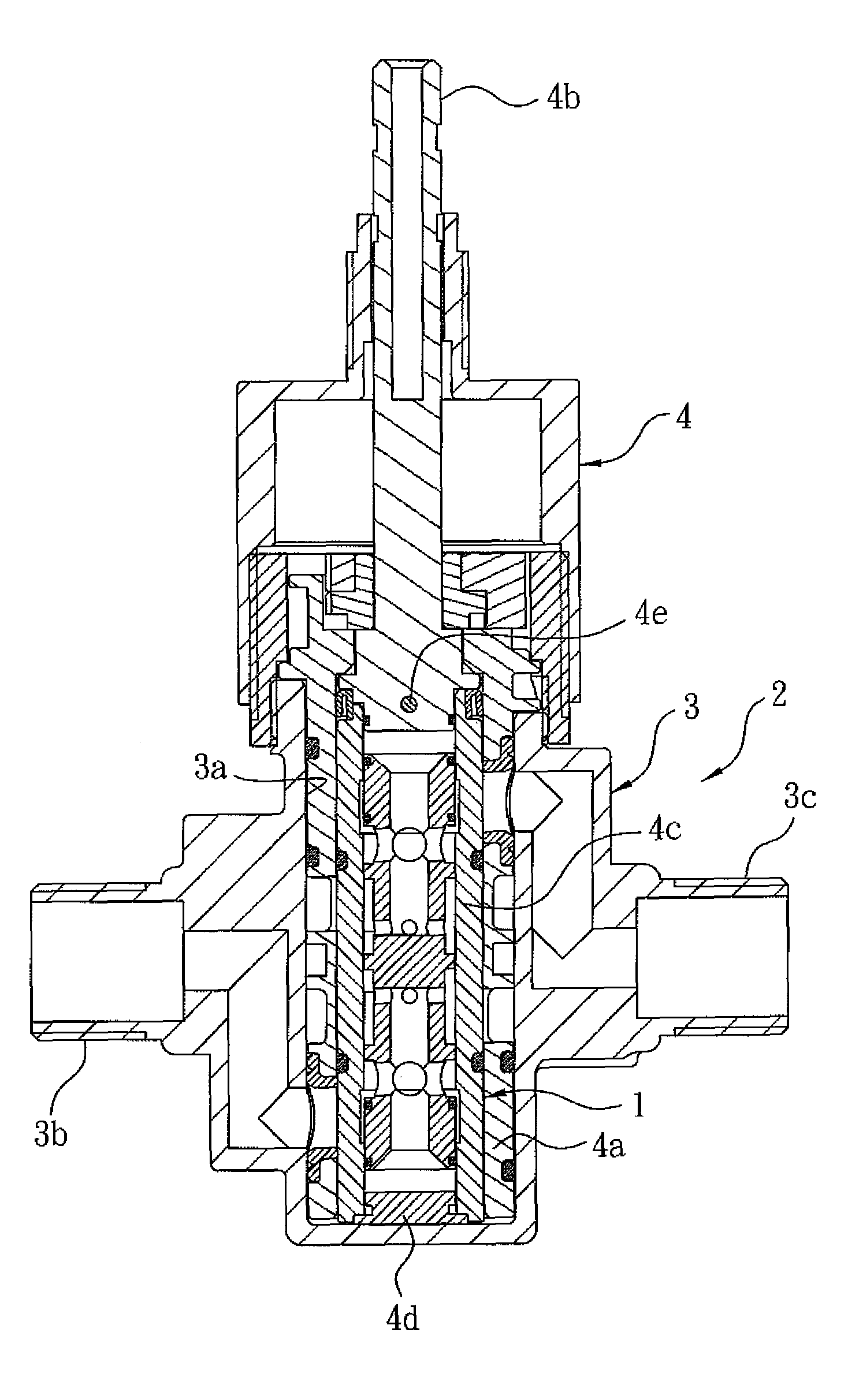
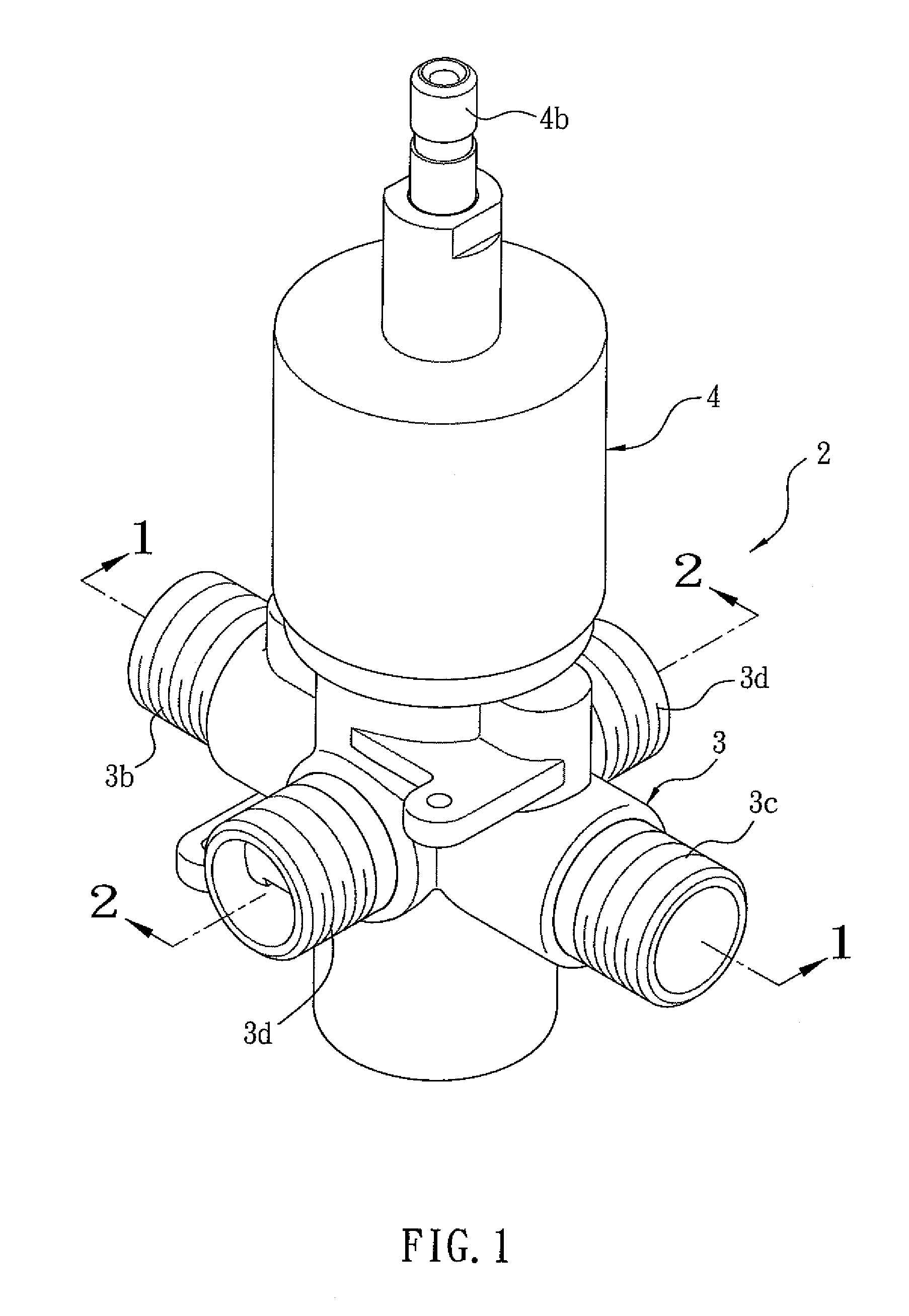
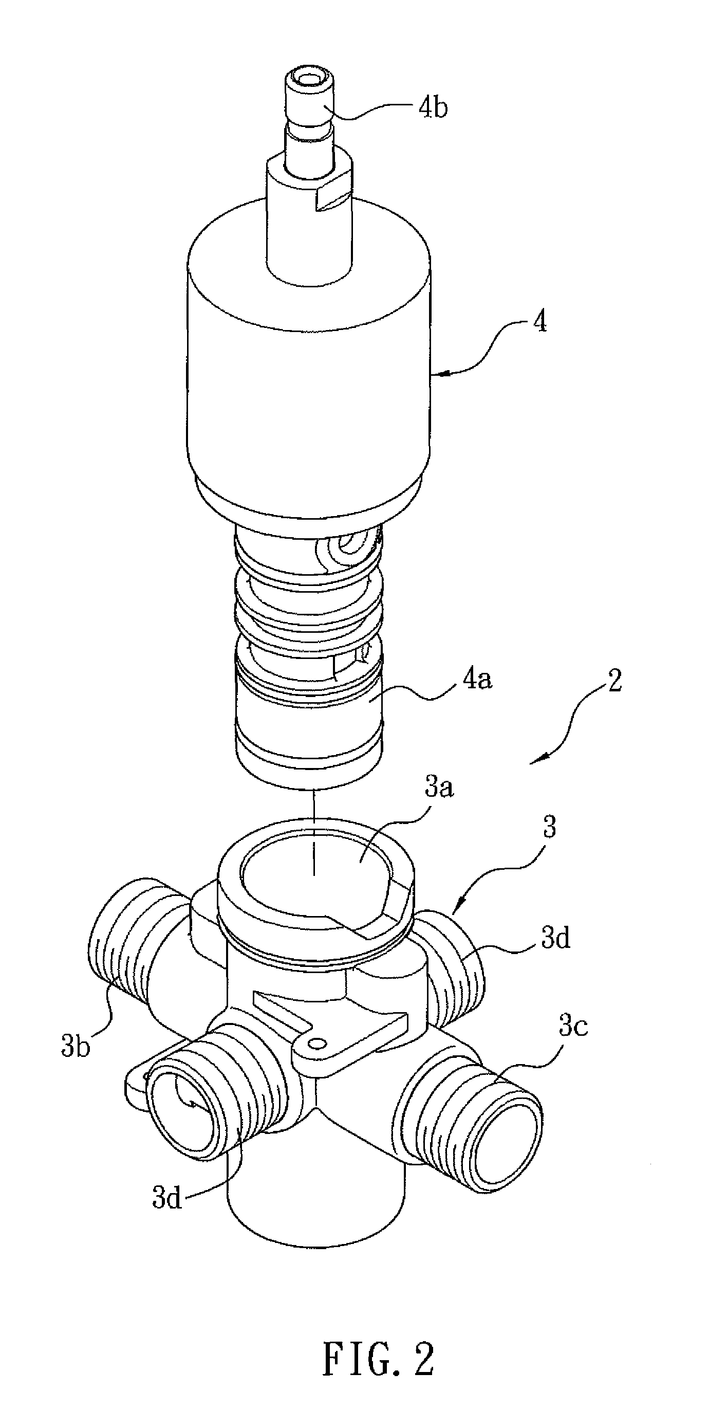
[0042]Referring further to FIGS. 1-4, a pressure balance valve 1 according to a first embodiment of the present invention is fixed on a water supply device 2. The water supply device 2 is a temperature control faucet and includes a faucet body 3, a temperature controlling valve 4, and the pressure balance valve 1 adjacent to the temperature controlling valve 4. The faucet body 3 includes a mounting groove 3a, a cold-water inflow channel 3b communicating with the mounting groove 3a, a hot-water inflow channel 3c, and two mixing outflow channels 3d. The temperature controlling valve 4 is mounted in the mounting groove 3a and includes a valve seat 4a, a central shaft 4b secured on the valve seat 4a, a thermostatic valve core 4c connected with a bottom end of the central shaft 4b and formed in a cylinder shape, and an end plug 4d for closing a bottom end of the thermostatic valve core 4c; wherein the bottom end of the central shaft 4b engages with a top end of the thermostatic valve cor...


PUM


Abstract

A pressure balance valve contains: a receiving chamber including an external cold-water inlet, an external hot-water inlet, an external cold-water outlet, and an external hot-water outlet; a valve core including a pressure sensing fence, a first ring portion and a second ring portion. Between the first ring portion and the pressure sensing fence is defined a cold-water pressure cavity, and between the second ring portion and the pressure sensing fence is defined a hot-water pressure cavity. The first ring portion has an internal cold-water inlet and an internal cold-water outlet, the second ring portion has an internal hot-water inlet and an internal hot-water outlet. The first ring portion also has at least one first fixing slot for fitting with at least one first resilient loop, and the second ring portion also has at least one second fixing slot for fitting with at least second resilient loop.

Description

FIELD OF THE INVENTION[0001]The present invention relates to a pressure balance valve.BACKGROUND OF THE INVENTION[0002]A conventional pressure valve is applied in various water supply devices, such as conventional or digital showering systems, as disclosed in U.S. Pat. No. 8,267,111 B2, US Publication Nos. US 2013 / 0042923 A1 and US 2012 / 0138177.[0003]The water supply device is normally a temperature control faucet and includes a thermostatic valve and a temperature sensing element for matching with the thermostatic valve; the thermostatic valve can adjust desired mixing ratio of cold water and hot water based on a preset showing temperature.[0004]The thermostatic valve can adjust the desired mixing ratio of the cold water and the hot water by adjusting a size of each of a cold-water orifice and a hot-water orifice. However, when the cold-water pressure of the cold-water orifice and the hot-water pressure of the hot-water orifice are not equal, the desired mixing ratio of the cold wa...

Claims


Application Information

Patent Timeline
Patent Type & Authority Patents(United States)
IPC IPC(8): G05D11/00G05D23/13
CPCG05D23/1313Y10T137/2521
Inventor KUO, CHUNGYUCHANG, CHUNGHSIANGCHANG, YUANHAOHONG, CHUWAN
Owner GLOBE UNION INDAL
Why Eureka
Try Eureka