Drill head for deep hole cutting

a drilling head and drilling head technology, applied in the direction of tool workpiece connection, manufacturing tools, transportation and packaging, etc., can solve the problems of deterioration of processing accuracy, deterioration of roundness, cylindricality, straightness, etc., of cutting holes, and achieve the effect of improving the pressure balance during drilling work

Inactive Publication Date: 2017-06-29
BOTEK PRAEZISIONSBOHRTECHNIK GMBH
View PDF7 Cites 0 Cited by
  • Summary
  • Abstract
  • Description
  • Claims
  • Application Information

AI Technical Summary

Benefits of technology

[0024]According to the present invention, guide pads 3A and 3B are mounted on respective specific two positions on the circumferential surface 1b at the head distal end side, so that the pressure balance during drilling work is further improved, whereby realizing high-accuracy drilling work. Other effects of the present invention will be clarified from the embodiments described hereinafter.

Problems solved by technology

However, the circumferential width of the margin portion is much narrower than the guide pads, so that the margin portion is abraded much faster than the guide pads according to an increase in the number of drilling works, and therefore, the pressure balance is gradually lost and the stable cutting state cannot be kept, and deterioration of processing accuracy leads to deterioration of the roundness, cylindricality, and straightness, etc., of a cutting hole.

Method used


Image

  • Drill head for deep hole cutting
  • Drill head for deep hole cutting
  • Drill head for deep hole cutting

Examples


second embodiment

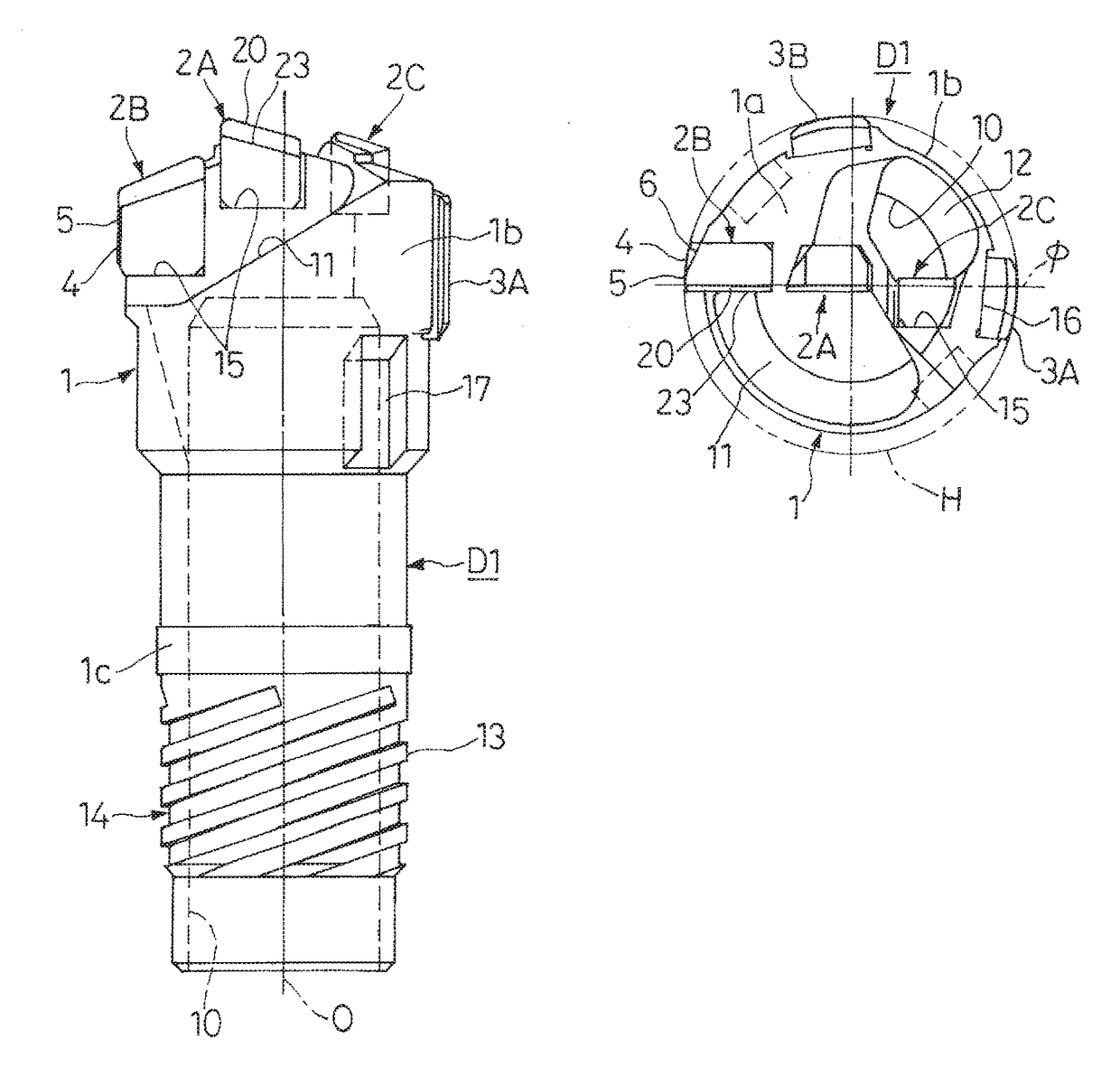
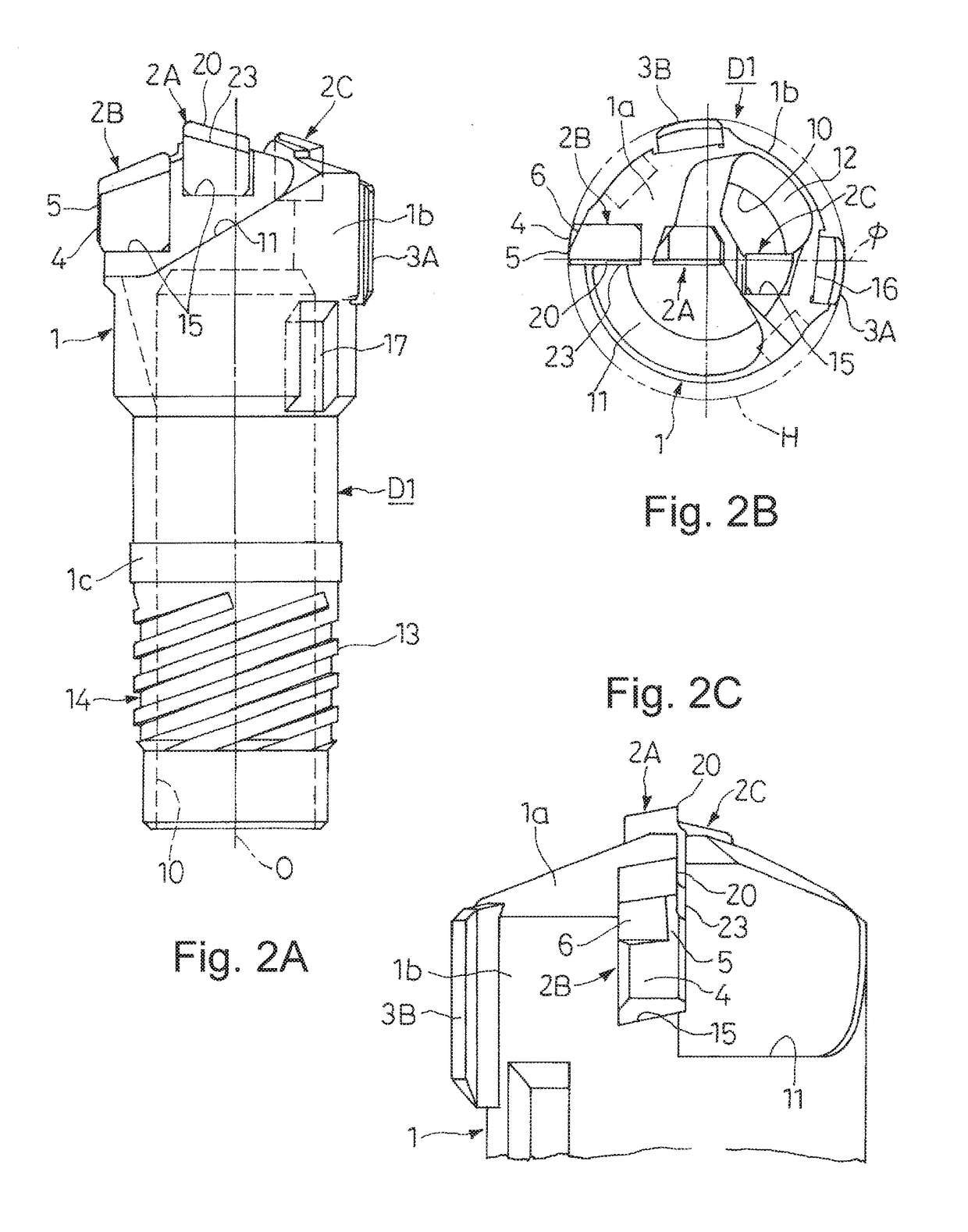
[0036]In deep-hole drilling work using the drill head D1, D2 for deep-hole drilling of the first or second embodiment, while rotating the drill head D1, D2 coupled to the above-mentioned boring bar (whose illustration is omitted) or a work material, a coolant supplied through a gap between the inner circumference of a cutting hole H and the outer circumferences of the hollow boring bar and the drill head D1, D2 is continuously fed to a cutting region, and cutting chips generated at the cutting region are caught in the coolant and discharged to the outside from the cutting chip discharge ports 11 and 12 of the drill head D1, D2 through the hollow inside portion of the boring bar.

[0037]In this drilling work, the guide pad portion 4 provided on the outer end surface of the circumferential portion cutting blade tip 2B slide-contacts with the inner circumference of a cutting hole H together with the guide pads 3A and 3B mounted on the outer circumferential surface 1b at the head distal e...

first embodiment

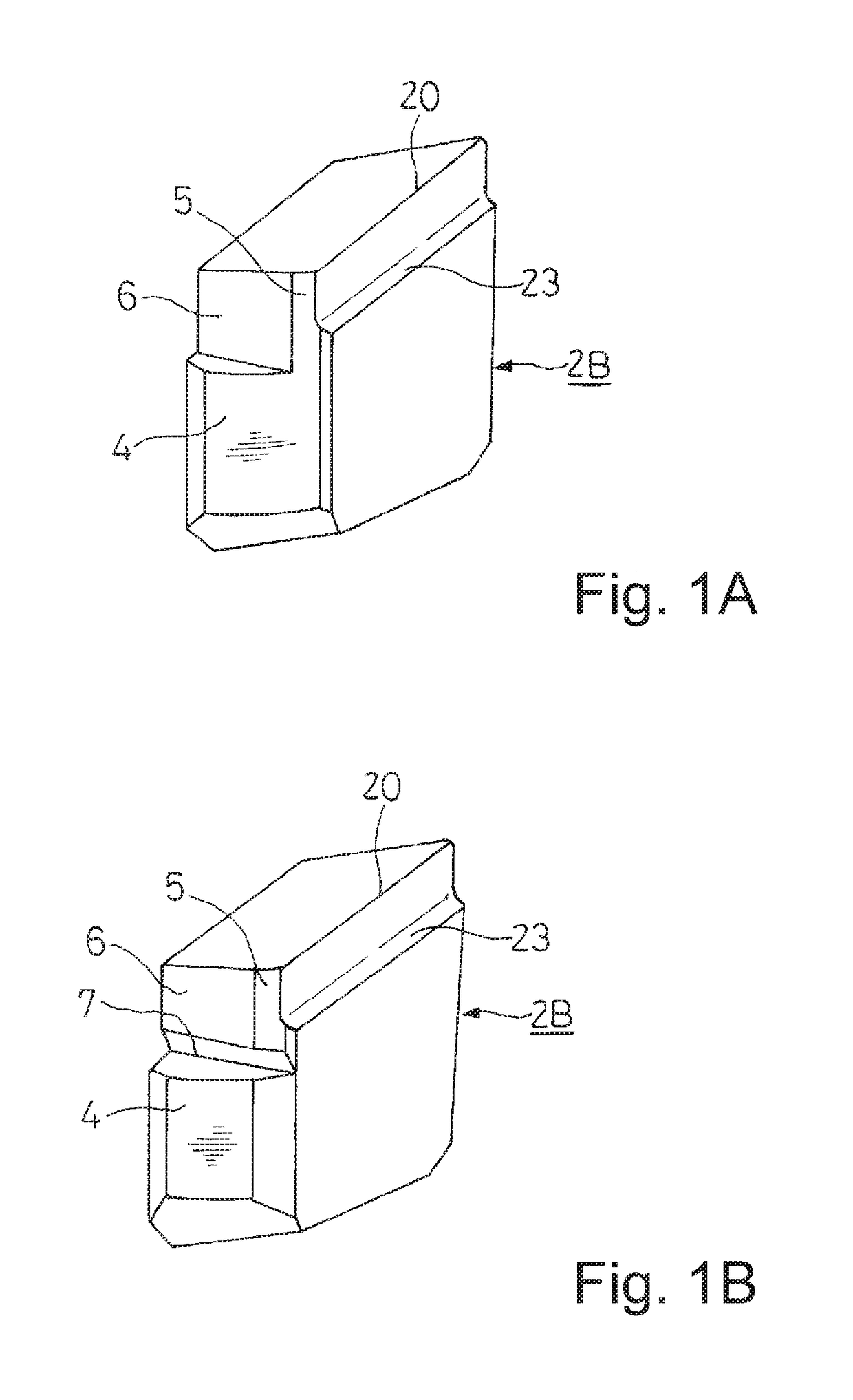
[0042]The cutting blade tip 2D in this drill head D3 has an inner end at a position slightly beyond the head shaft center O, a cutting blade 20 that is inclined upward in a two-step manner from the head circumferential side toward the head shaft center O side and further inclined downward toward the inner end side from the top portion, and a chip breaker 23 positioned on the front surface side and along the upward incline of the cutting blade 20. On the outer end surface of the cutting blade tip 2D, in the same manner as the cutting blade tip 2B of the first embodiment, a margin portion 5 facing the front edge in the cutting rotation direction and a flank face 6 to be spaced apart from the inner circumference of a cutting hole H (indicated by the imaginary line in FIG. 4B) and along the rear side in the cutting rotation direction are formed at an upper portion side, and at a lower portion side of the same outer end surface, a guide pad portion 4 is formed, and the margin portion 5 a...


PUM

PropertyMeasurementUnit
inclination angleaaaaaaaaaa
widthaaaaaaaaaa
circumferenceaaaaaaaaaa

Abstract

A drill head for deep-hole drilling includes cutting blade tips brazed to cutting chip discharge ports opened on a head distal end surface, guide pads mounted on a plurality of positions of the circumferential surface at the head distal end side, and a hollow inside portion made into a cutting chip discharge passage communicating with the cutting chip discharge ports. A guide pad portion having an arc surf ace that slide-contacts with the inner circumference of a cutting hole is formed on the outer end surface of the circumferential portion cutting blade tip.

Description

CROSS REFERENCE TO RELATED APPLICATIONS[0001]This application is a continuation of and Applicant claims priority under 35 U.S.C. §§120 of U.S. application Ser. No. 14 / 117,910 filed on Feb. 14, 2014, which application is a national stage application under 35 U.S.C. §371 of PCT Application No. PCT / JP2011 / 061181 filed on May 16, 2011, the disclosure of which is hereby incorporated by reference. The International Application under PCT article 21(2) was not published in English.TECHNICAL FIELD[0002]The present invention relates to a drill head for deep-hole drilling including a cutting blade tip mounted by brazing to face a cutting chip discharge port opened on a head distal end surface and a hollow inside portion made into a cutting chip discharge passage communicating with the cutting chip discharge port.BACKGROUND ART[0003]As this kind of drill head for deep-hole drilling, a divided-blade type as shown in FIG. 5A to FIG. 5C has been conventionally widely used. This drill head D0 inclu...

Claims


Application Information

Patent Timeline
Patent Type & Authority Applications(United States)
IPC IPC(8): B23B51/00B23B51/04
CPCB23B51/0054B23B51/0493B23B2240/08B23B2251/422B23B2251/56B23B51/0486B23B51/063B23B2251/44Y10T408/5586
Inventor NOMURA, TAKUJI
Owner BOTEK PRAEZISIONSBOHRTECHNIK GMBH
Why Eureka
Try Eureka