
Computing cluster with latency control

a technology of latency control and computing cluster, applied in the direction of program control, multi-programming arrangement, instruments, etc., can solve the problems of inability to execute tasks, limit the number of tasks that are ready to execute, and the execution time may not improve linearly in relation to the time, so as to achieve more robust control over the resources

Active Publication Date: 2016-02-16
MICROSOFT TECH LICENSING LLC
View PDF28 Cites 12 Cited by
  • Summary
  • Abstract
  • Description
  • Claims
  • Application Information

AI Technical Summary

Benefits of technology

The patent is about creating a model that takes into account the relationships between different tasks in a job. This model is built using a directed graph. The model also takes into account any failures that might occur during the execution of the job. This helps to make better decisions about how to allocate resources for the job, making it more robust against failures.

Problems solved by technology

As a result, some tasks cannot be executed until execution of other tasks is completed.
However, for each job, execution time may not improve linearly in relation to the number of processing resources allocated to the job.
Despite the fact that there may be many tasks left to execute, at any given time, there is a limit on the number of tasks that are ready to execute.
Allocating too many of the processing resources of the cluster to a single job may impact the performance of other jobs.
Allocating processing resources to jobs can be particularly challenging for an operator of a computing cluster when, through service level agreements with customers who have agreed to buy computing services from the cluster operator, the operator has committed to complete execution of certain jobs within a specified amount of time.
Such a commitment may be regarded as a service “guarantee,” and the service level agreement may entail a significant financial penalty if the job is not completed in accordance with the guarantee.
When the progress appears to be too slow to finish in time, more resources are added to the job.

Method used


Image

  • Computing cluster with latency control
  • Computing cluster with latency control
  • Computing cluster with latency control

Examples


Embodiment Construction

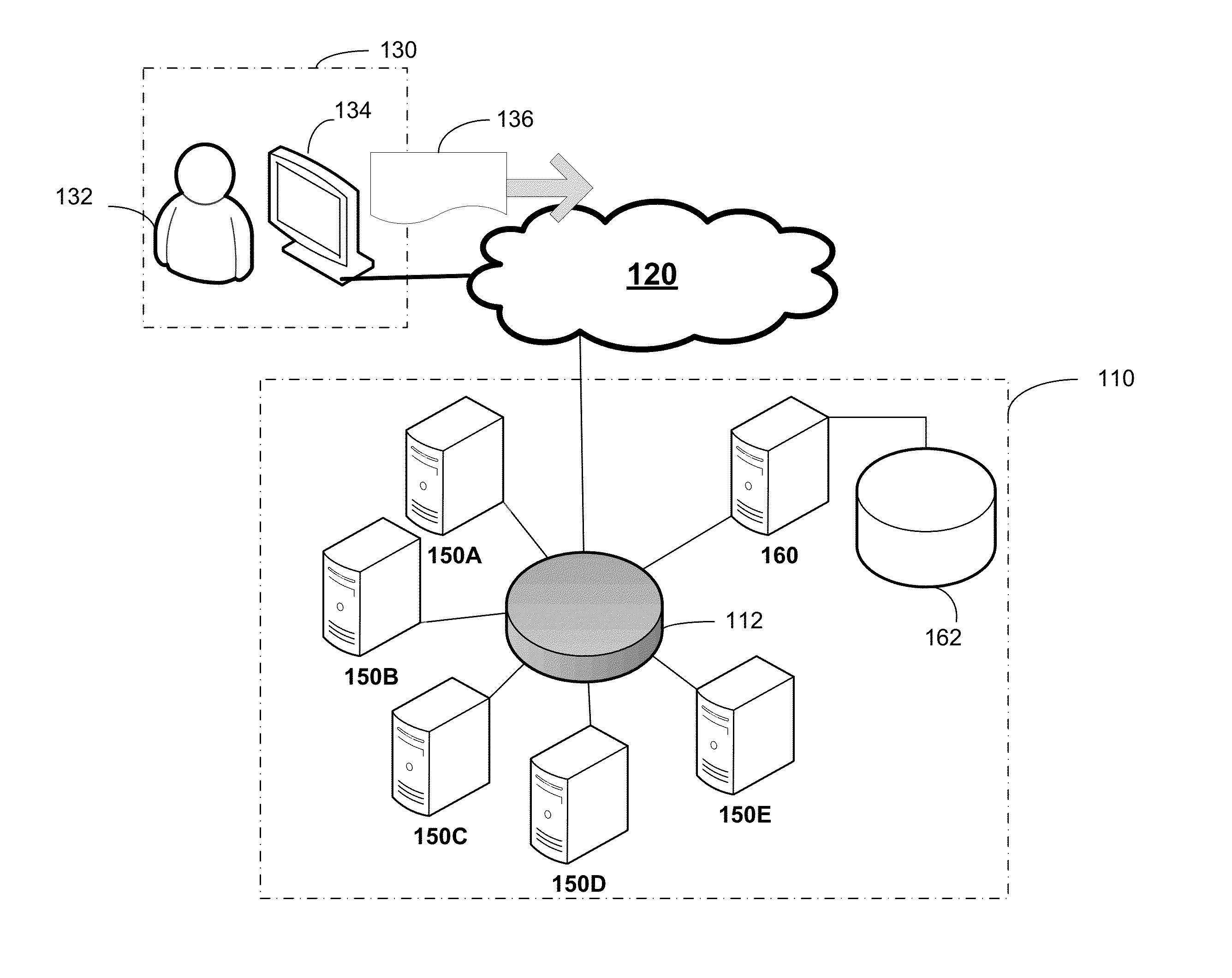
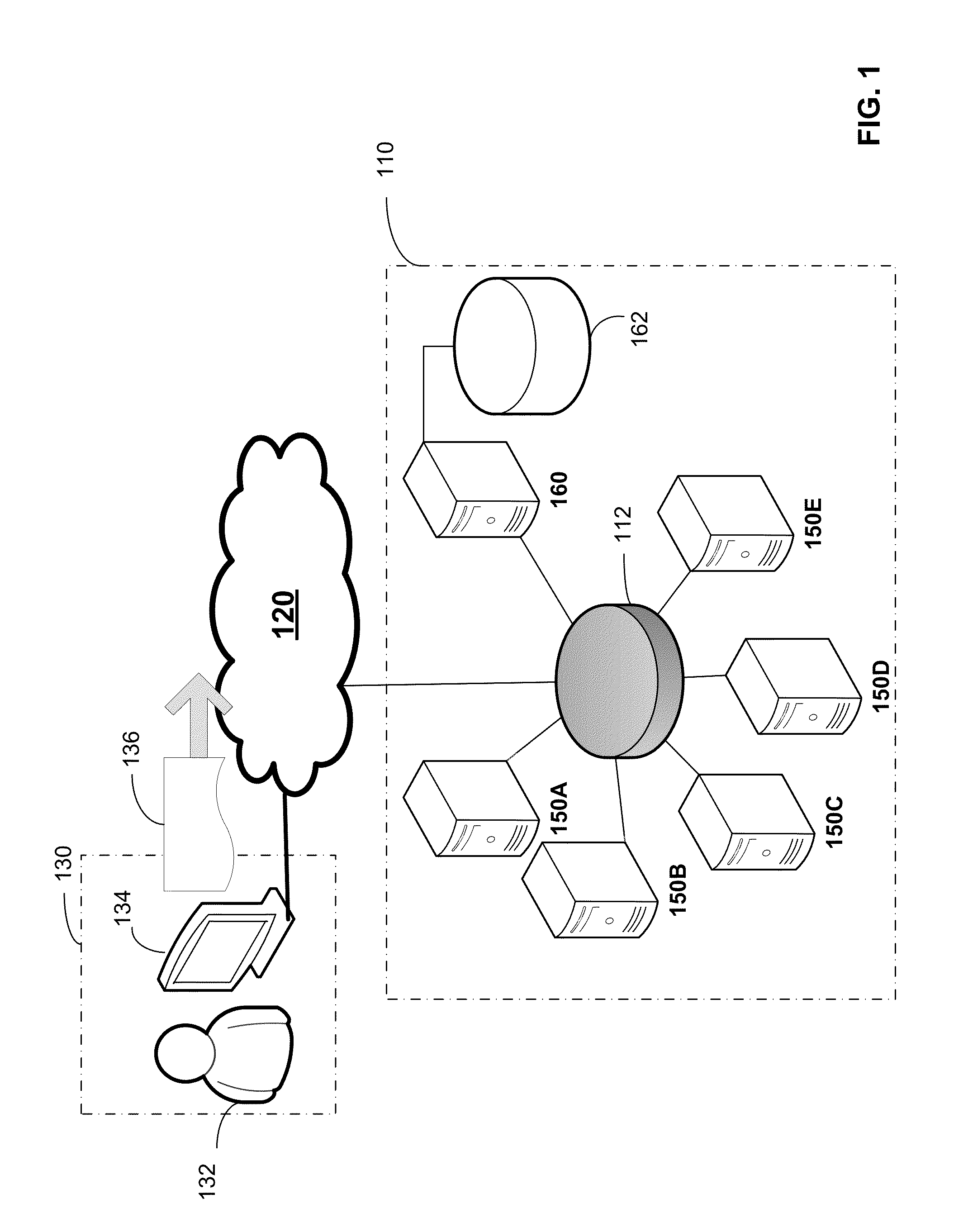
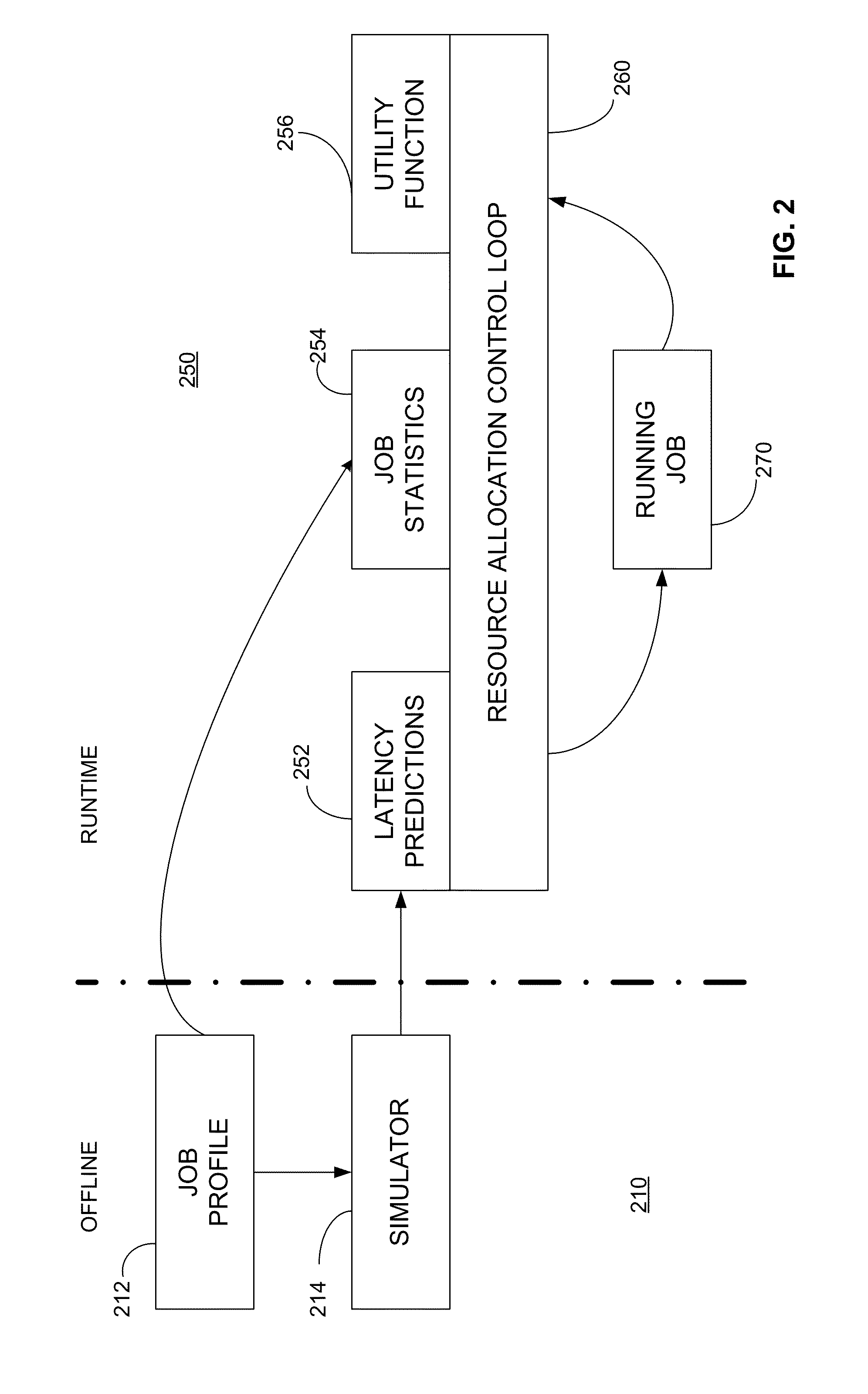
[0019]The inventors have recognized and appreciated benefits in operating a cluster computing platform that may be achieved by a scheduling policy that adaptively sets resource levels based on a robust predictive model of time to complete. The model may be used at job initiation. Alternatively or additionally, the model may thereafter be applied from time to time during execution of the job to align the amount of resources allocated to the job with an amount that, in accordance with the model, will lead to completion at or slightly before a target completion time. Such a policy may improve the efficiency of resource utilization by avoiding over-provisioning while ensuring that high priority jobs that have deadlines will be completed in accordance with those deadlines.

[0020]The target time for completion of the job at initiation, and at each time thereafter when resources are adjusted, may be determined in any suitable way. In some embodiments, the target time for completion may be d...


PUM


Abstract

A computing cluster operated according to a resource allocation policy based on a predictive model of completion time. The predictive model may be applied in a resource control loop that iteratively updates resources assigned to an executing job. At each iteration, the amount of resources allocated to the job may be updated based on of the predictive model so that the job will be scheduled to complete execution at a target completion time. The target completion time may be derived from a utility function determined for the job. The utility function, in turn, may be derived from a service level agreement with service guarantees and penalties for late completion of a job. Allocating resources in this way may maximize utility for an operator of the computing cluster while minimizing disruption to other jobs that may be concurrently executing.

Description

BACKGROUND[0001]Computing clusters are used to perform large processing jobs. The clusters contain multiple processing resources, which could be physical processors or virtual processors. A cluster also includes a scheduler that allocates the processing resources to jobs submitted to the cluster. The policy under which a scheduler operates impacts overall performance of the computing cluster.[0002]Jobs may contain multiple computational tasks that can be assigned for execution to multiple computing resources. For most large jobs that are “data-parallel jobs,” some tasks can be executed in parallel, while others are dependent on data generated from other tasks. As a result, some tasks cannot be executed until execution of other tasks is completed. For data-parallel jobs, allocating multiple processing resources to a job may allow more tasks to be executed in parallel, thereby improving execution time of the job. However, for each job, execution time may not improve linearly in relati...

Claims


Application Information

Patent Timeline
Patent Type & Authority Patents(United States)
IPC IPC(8): G06F9/48
CPCG06F9/4887
Inventor BODIK, PETERFERGUSON, ANDREW D.KANDULA, SRIKANTHBOUTIN, ERIC
Owner MICROSOFT TECH LICENSING LLC
Learn More