
Electronic device and method for DC-DC conversion with variable bias current

a technology of dc-dc converter and bias current control, which is applied in the direction of electric variable regulation, process and machine control, instruments, etc., can solve the problems of dc-dc converters that tend to trigger erroneously, and achieve the effect of reducing the susceptibility to false triggers

Active Publication Date: 2015-03-03
TEXAS INSTR INC
View PDF8 Cites 11 Cited by
  • Summary
  • Abstract
  • Description
  • Claims
  • Application Information

AI Technical Summary

Benefits of technology

This patent is about a new electronic device and method for DC-DC conversion that reduces the risk of false triggers due to changes in bias current. The device includes a switch mode DC-DC converter with a comparator to generate driving signals for power switches. The comparator can switch between PWM mode and PFM mode depending on the load being driven. The bias current of the comparator can be adjusted in response to changes in load, and a gradual and slow reduction of bias current helps to prevent unintended mode changes. The device also includes a compensation for loss of comparator gain when the bias current is reduced. Overall, this patent provides a more reliable and precise control of DC-DC conversion.

Problems solved by technology

Prior art switch mode DC-DC converters tend to trigger erroneously if the bias current is changed.

Method used


Image

  • Electronic device and method for DC-DC conversion with variable bias current
  • Electronic device and method for DC-DC conversion with variable bias current
  • Electronic device and method for DC-DC conversion with variable bias current

Examples


Embodiment Construction

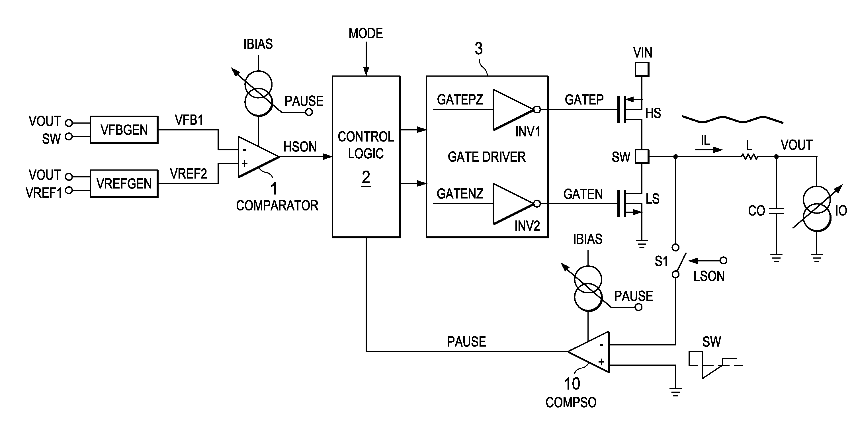
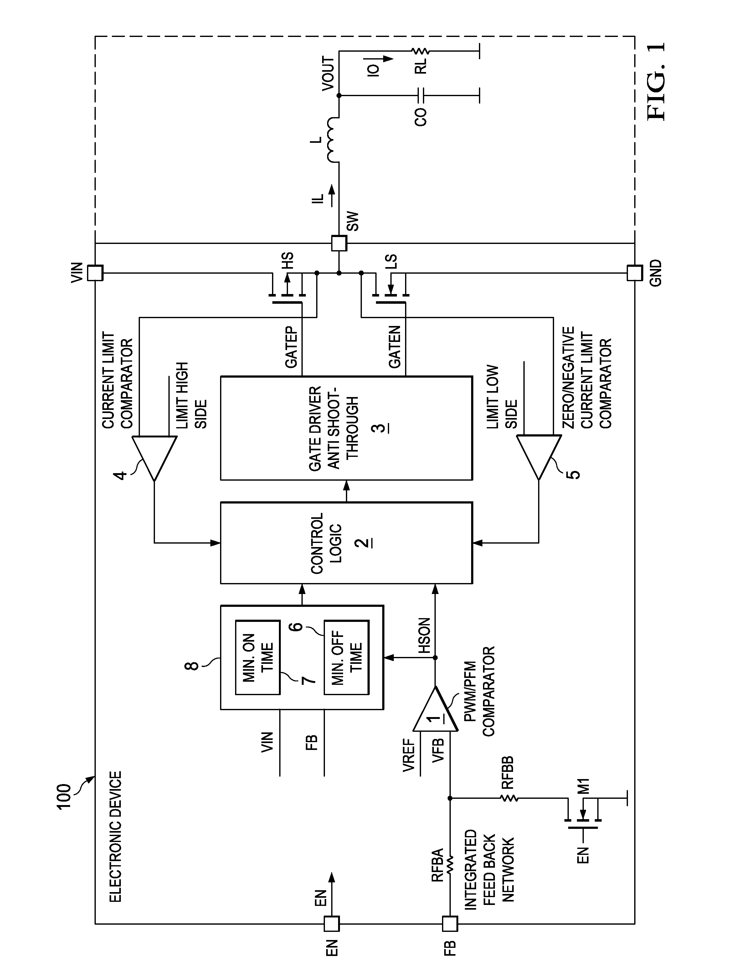
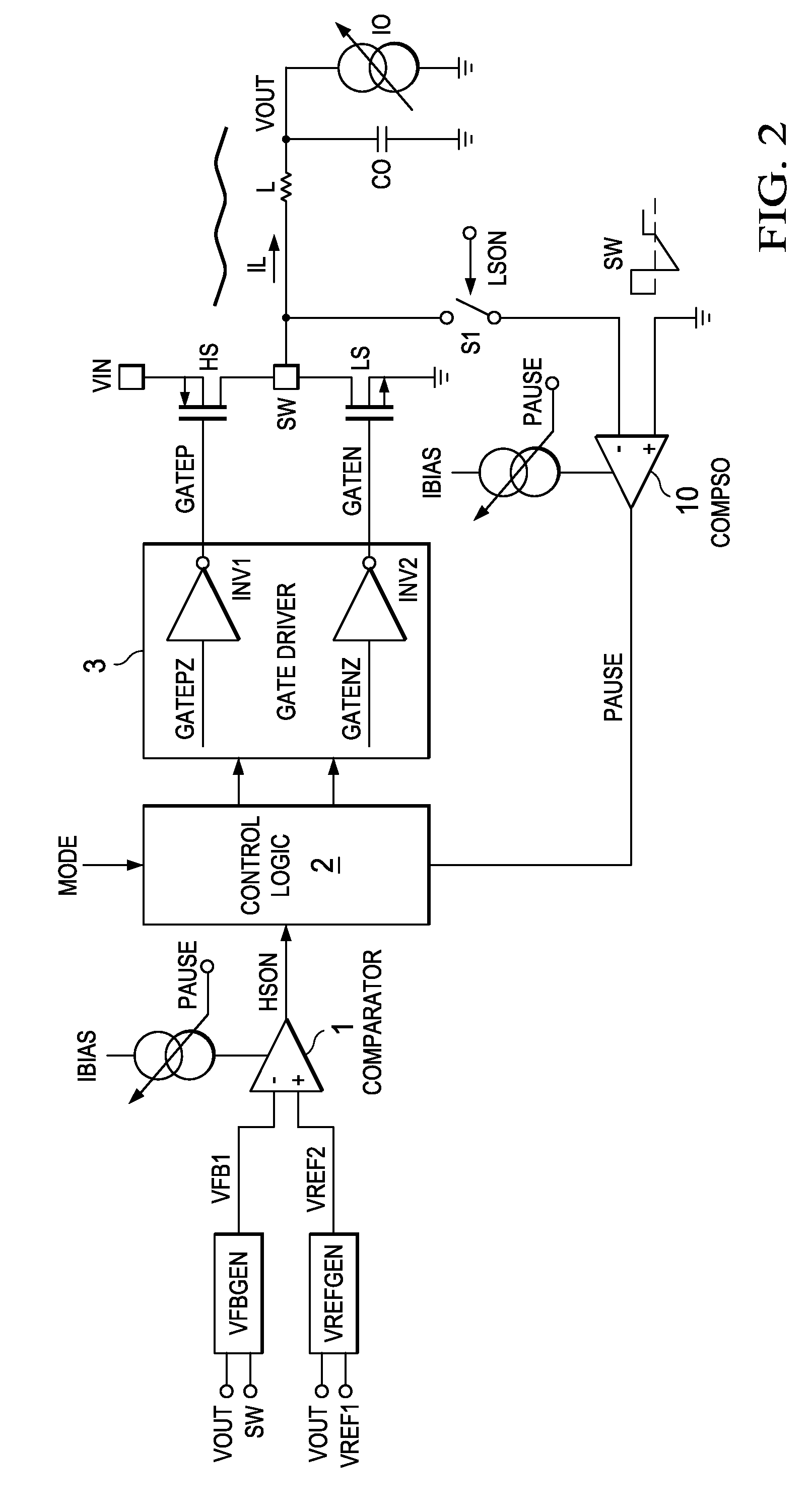
[0016]FIG. 1 shows a simplified circuit and block diagram of an electronic device 100 to which the aspects of the invention apply. The electronic device can comprise or substantially be an integrated circuit. The electronic device can be configured to perform DC-DC conversion. The solid line suggests how integrated and external components can be arranged. However, other configurations are also possible. This embodiment relates to a DC-DC converter with two power switches HS and LS. Switch HS is referred to as high side switch and implemented with a PMOS transistor. The other switch LS is referred as the low side switch and implemented with an NMOS transistor. The high side switch HS is coupled with one side of its channel to receive the primary input voltage VIN. The low side switch LS is coupled with one side of its channel to the other side of the channel of the high side switch HS. This node is the switching node SW. The other side of the channel of the low side switch is coupled...


PUM


Abstract

The invention relates to an electronic device and a method for DC-DC conversion using a comparator for generating an output signal for driving a power switch of a switch mode DC-DC converter. The electronic device is configured to reduce a bias current of the comparator with a first slope in response to a decreasing load and to increase the bias current of the comparator with a second slope in response to an increasing load, wherein the second slope is steeper than the first slope.

Description

CROSS-REFERENCE TO RELATED APPLICATIONS[0001]This patent application claims priority from German Patent Application No. 10 2009 024 159.0, filed Jun. 8, 2009, which is incorporated herein by reference in its entirety.FIELD OF THE INVENTION[0002]The present invention relates to an electronic device and a method for switch mode DC-DC conversion with bias current control for reducing power consumption.BACKGROUND OF THE INVENTION[0003]Low quiescent current switch mode converters require that the bias currents in some or all sub-circuits are reduced if the load on the secondary side of the DC-DC converter decreases. A decreasing load means that the load current (or the output current) of the DC-DC converter also decreases. Low bias currents for low loads provide low quiescent currents of the DC-DC converter and therefore low power consumption. Prior art switch mode DC-DC converters tend to trigger erroneously if the bias current is changed. In order to prevent these false triggers, conve...

Claims


Application Information

Patent Timeline
Patent Type & Authority Patents(United States)
IPC IPC(8): H02M3/157H02M1/00H02M1/32H02M3/158
CPCH02M3/157H02M1/32H02M3/1588H02M2001/0032Y02B70/1466Y02B70/10H02M1/0032
Inventor SCOONES, KEVINTHIELE, GERHARDGIBSON, NEIL
Owner TEXAS INSTR INC
Learn More