Test apparatus and test method

a test apparatus and test method technology, applied in the field of test apparatus, can solve the problems of long test time and a certain amount of switching time for the operation of condition switching

Active Publication Date: 2016-02-16
ADVANTEST CORP
View PDF13 Cites 20 Cited by
  • Summary
  • Abstract
  • Description
  • Claims
  • Application Information

AI Technical Summary

Benefits of technology

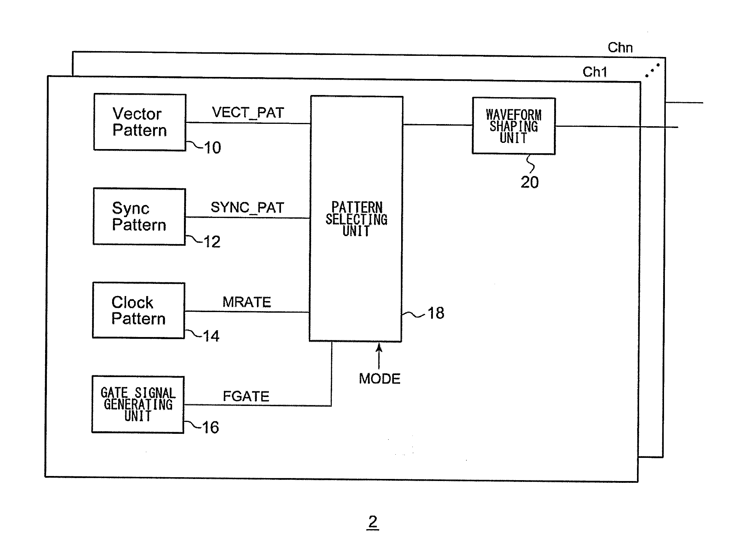
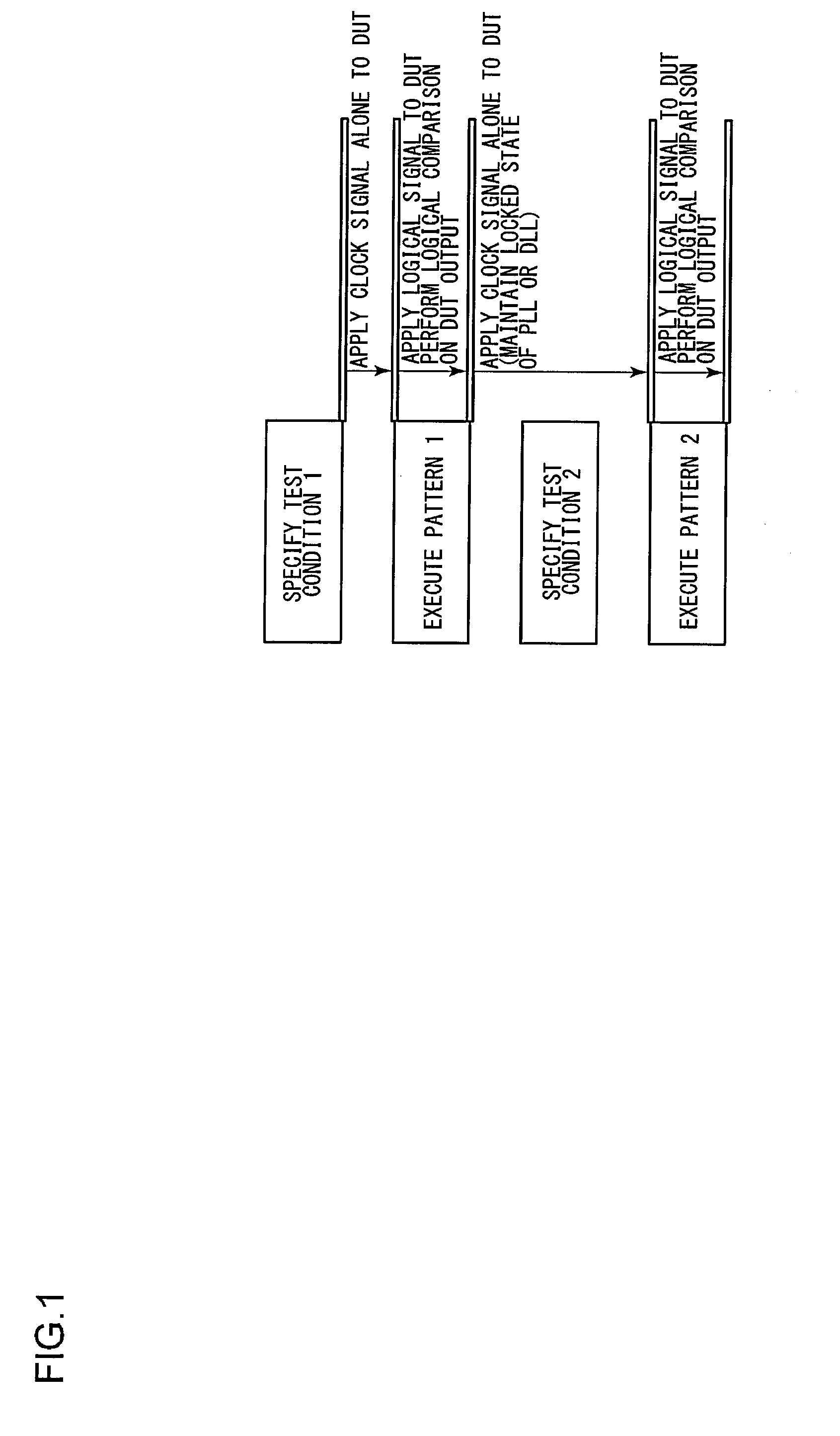
[0008]Conceivable methods used to solve such a problem include a method in which, during a period of time in which the supply of a test pattern is stopped, i.e., during a period of time in which the test condition is switched, a clock signal is continuously output to the clock input pin of the DUT. This ensures that the PLL circuit or the DLL circuit built into the DUT is kept in the locked state. FIG. 1 is a flowchart showing an operation for maintaining the locked state of the PLL / DLL circuit built into the DUT.

Problems solved by technology

In this case, such a test condition switching operation requires a certain amount of switching time.
Thus, before a test pattern is supplied in the next operation, there is a need to again lock the PLL circuit or the DLL circuit, leading to a problem of a long test time.

Method used


Image

  • Test apparatus and test method
  • Test apparatus and test method
  • Test apparatus and test method

Examples


Embodiment Construction

[0020]The invention will now be described based on preferred embodiments which do not intend to limit the scope of the present invention but exemplify the invention. All of the features and the combinations thereof described in the embodiment are not necessarily essential to the invention.

[0021]In the present specification, a state represented by the phrase “the member A is connected to the member B” includes a state in which the member A is indirectly connected to the member B via another member that does not affect the electric connection therebetween, in addition to a state in which the member A is physically and directly connected to the member B. Similarly, a state represented by the phrase “the member C is provided between the member A and the member B” includes a state in which the member A is indirectly connected to the member C, or the member B is indirectly connected to the member C via another member that does not affect the electric connection therebetween, in addition t...


PUM


Abstract

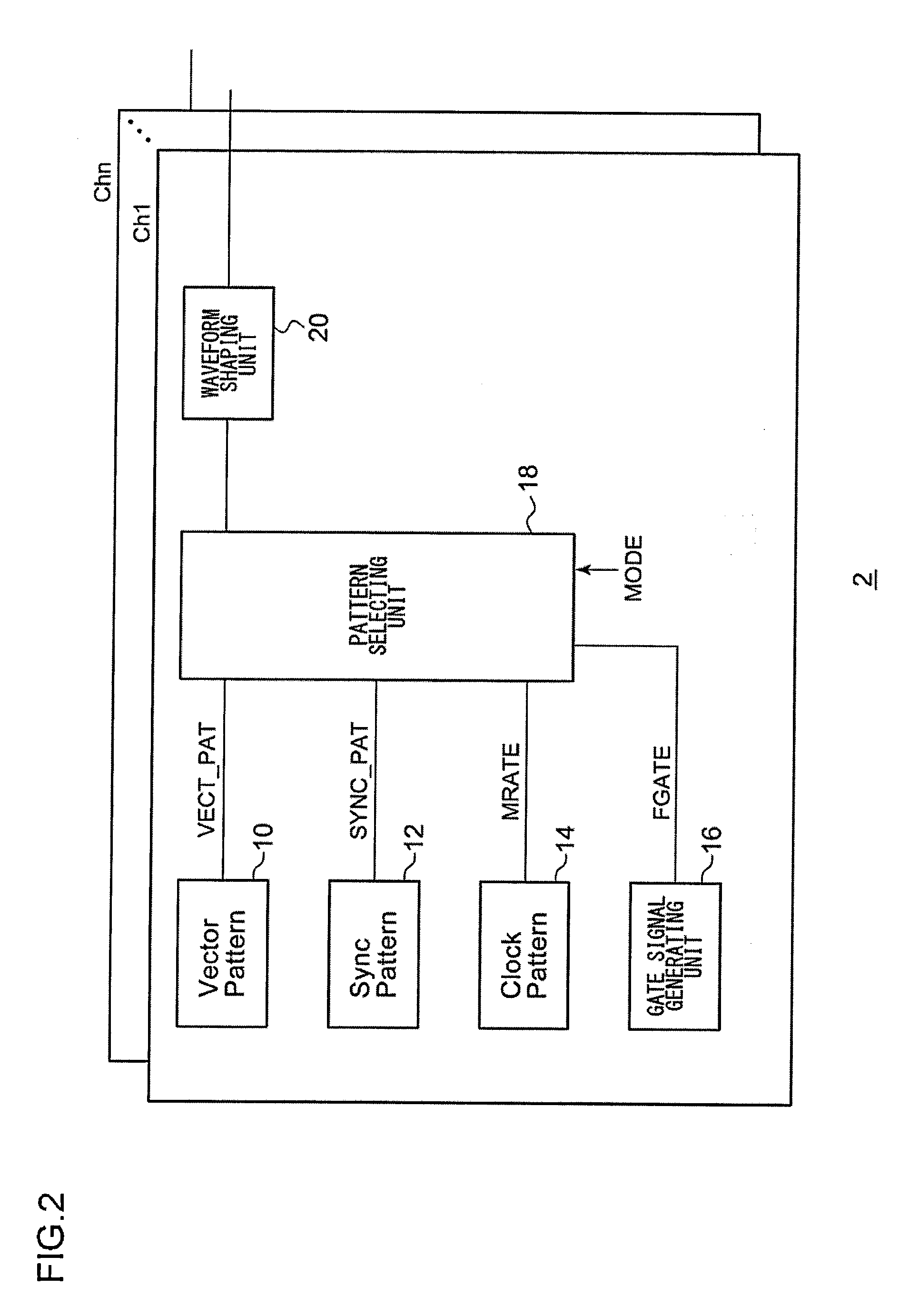
A synchronization pattern generating unit generates a synchronization pattern required for a clock recovery unit which has been built into a DUT to maintain a link with an external circuit. A gate signal generating unit generates a gate signal which is asserted in a period in which a vector pattern is to be supplied to the DUT. In a first mode, a pattern selecting unit is configured such that it outputs the vector pattern during a period in which the gate signal is asserted and outputs a fixed output level during a period in which the gate signal is negated. In a second mode, the pattern selecting unit is configured such that it outputs the vector pattern during a period in which the gate signal is asserted and outputs the synchronization pattern during a period in which the gate signal is negated.

Description

CROSS REFERENCE TO RELATED APPLICATIONS[0001]This application is a continuation of International Application No. PCT / JP2010 / 004444, filed on Jul. 7, 2010, the disclosure of which is hereby incorporated by reference in it entirety.BACKGROUND OF THE INVENTION[0002]1. Field of the Invention[0003]The present invention relates to a test apparatus configured to test a semiconductor device.[0004]2. Description of the Related Art[0005]After a semiconductor device is manufactured, a semiconductor test apparatus (which will also be referred to simply as a “test apparatus” hereafter) is used in order to test whether or not the semiconductor device thus manufactured operates normally. The test apparatus is configured to receive a signal (signal under test) output from a DUT (device under test), and to compare the signal under test with an expected value so as to judge the quality (Pass / Fail) of the DUT. Also, the test apparatus is configured to measure the amplitude margin and / or the timing mar...

Claims


Application Information

Patent Timeline
Patent Type & Authority Patents(United States)
IPC IPC(8): H04B3/46G01R31/319G06F17/00G01R31/26G01R31/317
CPCG06F17/00G01R31/2601G01R31/31908G01R31/31726G01R29/00G01R31/26G01R31/3177G01R31/3183
Inventor TSUTO, MASARU
Owner ADVANTEST CORP
Why Eureka
Try Eureka