Tri-gate display panel

Active Publication Date: 2016-02-16
TCL CHINA STAR OPTOELECTRONICS TECH CO LTD
View PDF81 Cites 3 Cited by
  • Summary
  • Abstract
  • Description
  • Claims
  • Application Information

AI Technical Summary

Benefits of technology

The present invention aims to improve the display quality of tri-gate display panels by changing the wiring mode on the panel and designing the source fanout area with less restricted impedance. This results in reduced charging differences between sub-pixels representing different colors, thus relieving color shifting in blending pictures and improving display quality. In addition, the design allows for panels with narrow frames to be easily designed.

Problems solved by technology

However, a fanout area thus designed generally has a large resistance difference (Rmax−Rmin) therein.
In practice, the major problem caused by a large impedance difference in the fanout area at the source side is color shifting at two sides of the panel during display of a blending picture.
Since large impedance in the fanout area would cause rather sever RC delay of a signal, the charging condition of a first sub-pixel would be worse than that of a second sub-pixel.
Especially for the fanout area having the largest wiring impedance, i.e., two sides of the panel, charging differences between sub-pixels would lead to color shifting.

Method used


Image

  • Tri-gate display panel
  • Tri-gate display panel
  • Tri-gate display panel

Examples


Embodiment Construction

[0026]The present disclosure will be explained in details with reference to the embodiments and the accompanying drawings, whereby it can be fully understood how to solve the technical problem by the technical means according to the present disclosure and achieve the technical effects thereof, and thus the technical solution according to the present disclosure can be implemented. It is important to note that as long as there is no conflict, all the technical features mentioned in all the embodiments may be combined together in any manner, and the technical solutions obtained in this manner all fall within the scope of the present disclosure.

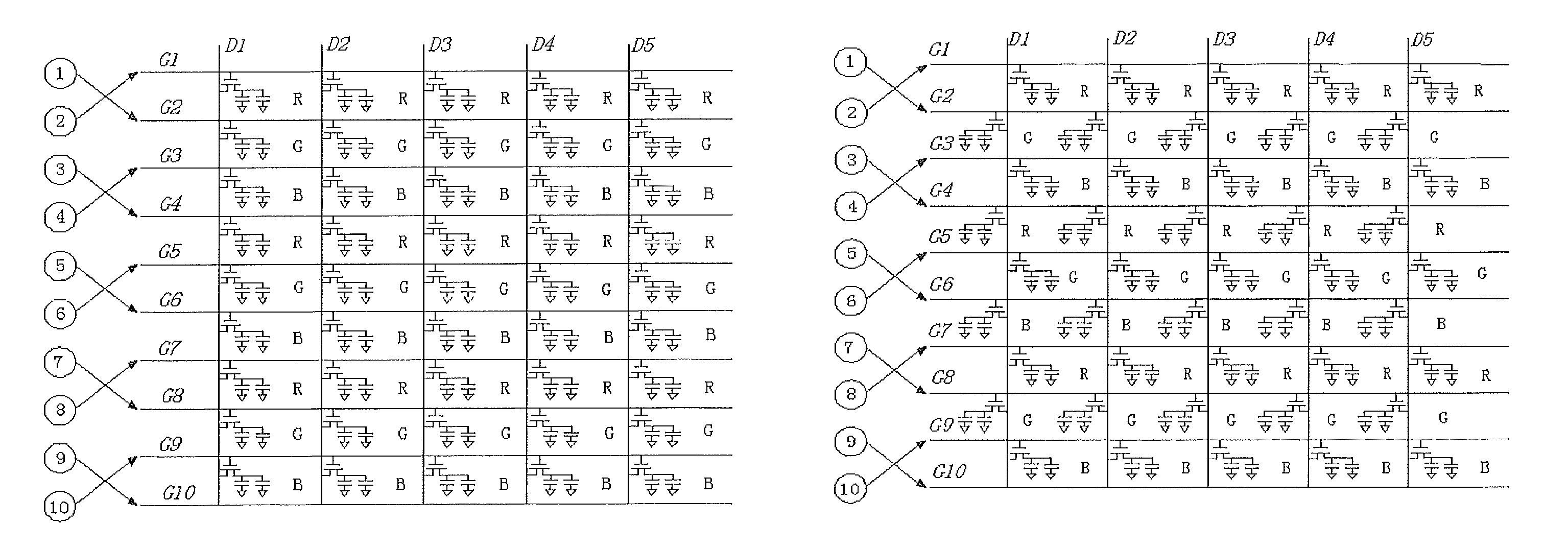
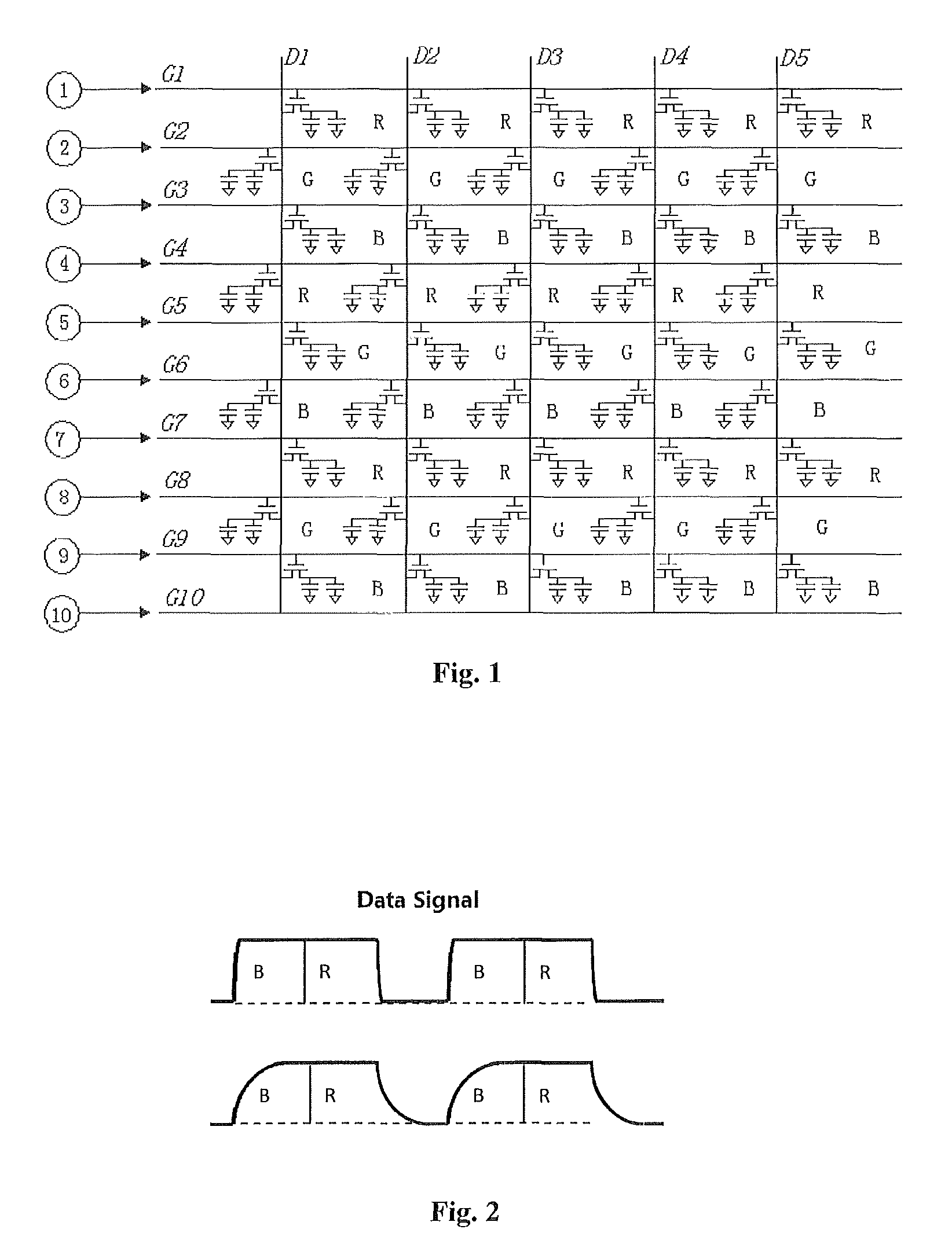
[0027]FIG. 1 shows a wiring diagram of fanout terminals and pixel units of a conventional tri-gate display panel which adopts the design of a high pin count at a source side. In the figure, D1 to D5 represent data lines, while G1 to G10 represent gate lines. The circled numbers indicate serial numbers of fanout lines.

[0028]FIG. 2 shows charging c...


PUM


Abstract

A tri-gate display panel is provided, comprising: a plurality of pixel units each including three sub-pixel units for displaying different colors, wherein each sub-pixel unit is provided with a thin film transistor which has its source connected to a charge electrode of the sub-pixel unit via a capacitor of the sub-pixel unit per se; a plurality of gate lines which are successively arranged along a first direction of the display panel, so as to connect to gates of the thin film transistors of corresponding sub-pixel units; a plurality of data lines, which are successively arranged along a second direction of the display panel, so as to connect to drains of the thin film transistors of corresponding sub-pixel units; and a fanout area including a plurality of fanout lines, wherein output terminals of the plurality of fanout lines are arranged in accordance with the plurality of gate lines and are in pair-wise cross connections to the plurality of gate lines. According to the present disclosure, charging differences between different colors of sub-pixels can be reduced. Hence, color shifting of a blending picture at two sides of the panel can be avoided and display effects can be improved.

Description

CROSS-REFERENCE TO RELATED APPLICATIONS[0001]The present application claims benefit of Chinese patent application CN 201410559614.3, entitled “Tri-gate display panel” and filed on Oct. 20, 2014, the entirety of which is incorporated herein by reference.FIELD OF THE INVENTION[0002]The present disclosure relates to the technical field of displays, and in particular to a tri-gate display panel.BACKGROUND OF THE INVENTION[0003]In designing a conventional tri-gate panel, the design of a high pin count is commonly adopted at a source side in order to save costs. For example, only one set of fanout terminals and one integrated circuit (IC) chip can be used at the source side. However, a fanout area thus designed generally has a large resistance difference (Rmax−Rmin) therein.[0004]In practice, the major problem caused by a large impedance difference in the fanout area at the source side is color shifting at two sides of the panel during display of a blending picture. With respect to displa...

Claims


Application Information

Patent Timeline
IPC IPC(8): H01L27/12H01L33/38
CPCH01L33/38H01L27/124H01L27/1214H01L27/1255G02F1/13452G09G3/3607G09G3/3677G09G2300/0426G09G3/3659G09G2300/0452G09G2320/0242G09G3/18
Inventor DU, PENG
Owner TCL CHINA STAR OPTOELECTRONICS TECH CO LTD
Why Eureka
Try Eureka