Mixing optical zoom system with moving gate and gobo

Inactive Publication Date: 2013-06-27
KONINKLIJKE PHILIPS ELECTRONICS NV
View PDF3 Cites 6 Cited by
  • Summary
  • Abstract
  • Description
  • Claims
  • Application Information

AI Technical Summary

Benefits of technology

[0005]It is with respect to the above considerations and others that the present invention has been made. The present invention seeks to mitigate, alleviate or eliminate the above-mentioned disadvantage. In particular, it would be desirable to achieve an illumination device which enables projection of a shadow/light pattern onto a target surface. It would further be desirable

Problems solved by technology

However, color mixing performance often deteriorates when the lens or optics of the hard edge spot luminary is brought out of focus, which may result in undesired color fring

Method used


Image

  • Mixing optical zoom system with moving gate and gobo
  • Mixing optical zoom system with moving gate and gobo
  • Mixing optical zoom system with moving gate and gobo

Examples


Example

[0073]In the accompanying drawings, the same reference numerals denote the same or similar elements throughout the views.

DETAILED DESCRIPTION

[0074]The present invention will now be described more fully hereinafter with reference to the accompanying drawings, in which exemplifying embodiments of the invention are shown. This invention may however be embodied in many different forms and should not be construed as limited to the embodiments set forth herein; rather, these embodiments are provided by way of example so that this disclosure will convey the scope of the invention to those skilled in the art. Furthermore, like numbers refer to like or similar elements throughout.

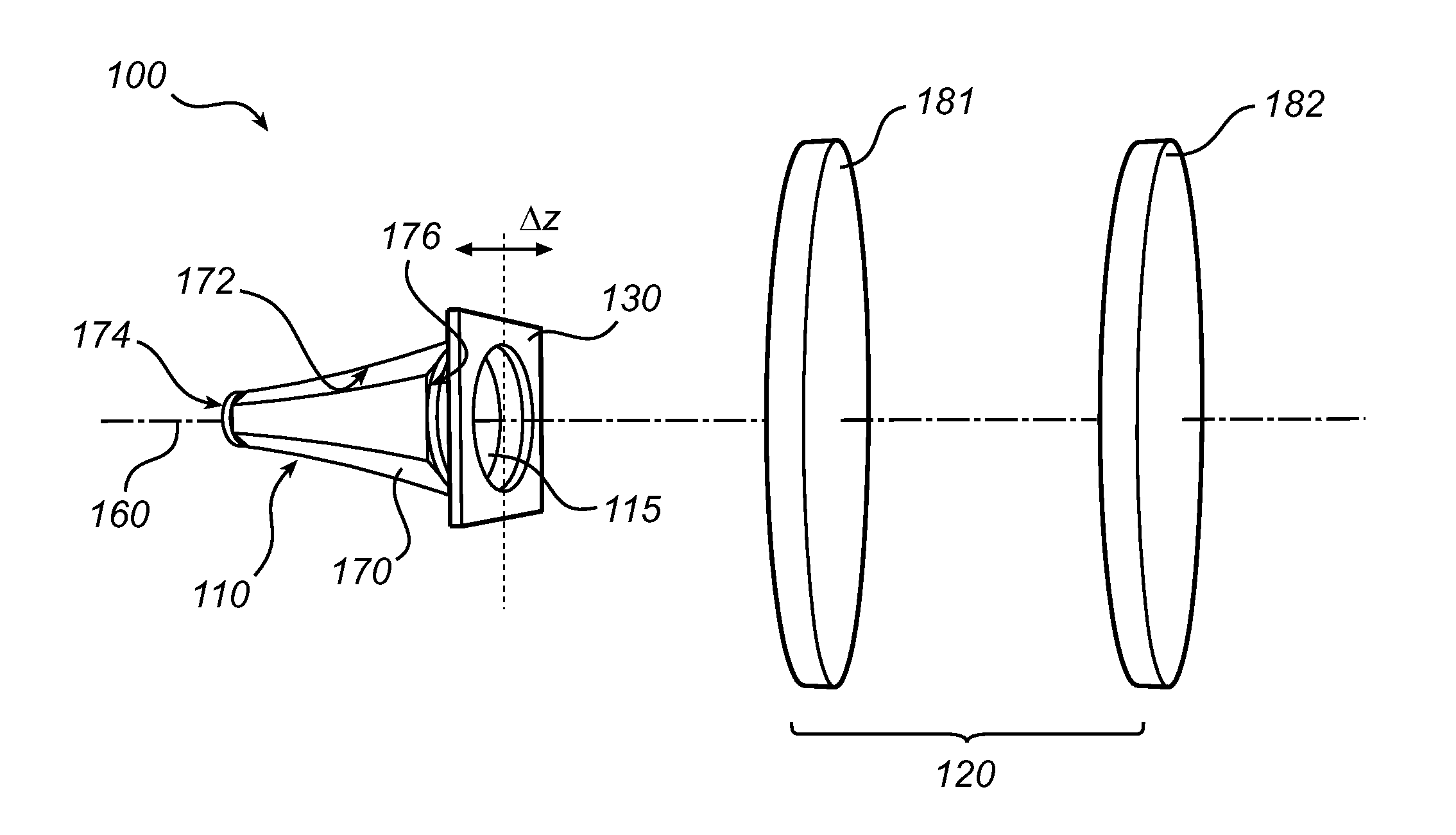
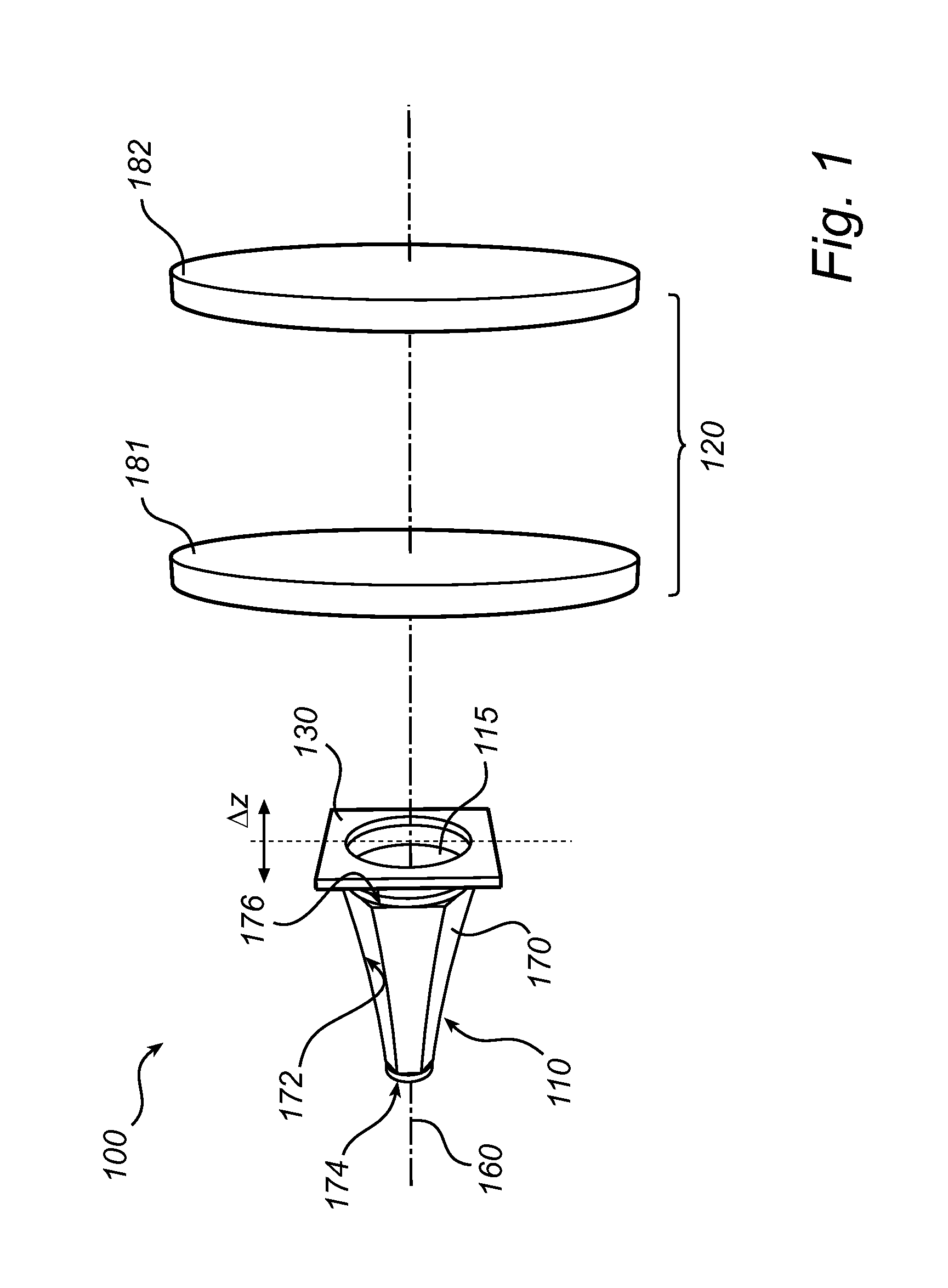
[0075]Referring now to FIG. 1, there is shown a schematic exploded view of an illumination device 100 according to an exemplifying embodiment of the present invention.

[0076]The illumination device comprises a collimation module 110, the collimation module 110 comprising a tubular reflector 170 having a reflective in...


PUM


Abstract

An illumination device (100) is disclosed. The illumination device (100) comprises a collimation module (110) configured to collimate light, a lens assembly (120) configured to controllably focus/defocus light, and an intermediate module (130) arranged between the collimation module (110) and the lens assembly (120) such as to receive collimated light output from the collimation module (110), wherein at least some light output from the intermediate module (130) impinges on the lens assembly (120).

Description

FIELD OF THE INVENTION[0001]The present invention is generally related to lighting applications. In particular, the present invention relates to an illumination device.BACKGROUND OF THE INVENTION[0002]In spot illumination applications, such as in entertainment lighting applications, in scene setting or other atmosphere creating lighting, colored light may be of importance. Examples of such applications are stage lighting, theatre lighting, studio lighting, architectural lighting (e.g., for city beautification), lighting in hotels, restaurants, etc. Colored light is often achieved by means of a combination of light sources emitting white light (also referred to as white light sources) and colored filters.[0003]Lately, as an alternative, illumination systems with colored light sources, i.e. light sources emitting colored light, such as light emitting diodes (LEDs), have been developed. Thus, colored filters may not be required. In illumination systems with colored light sources, the c...

Claims


Application Information

Patent Timeline
IPC IPC(8): F21V14/00
CPCF21S10/007F21V14/08F21W2131/406F21Y2101/02F21Y2113/005F21V5/008F21V5/04F21V7/04F21Y2105/008F21V14/00F21Y2105/00F21Y2115/10F21Y2115/15F21Y2113/13F21V5/10
Inventor TUKKER, TEUNIS WILLEMKURT, RALPH
Owner KONINKLIJKE PHILIPS ELECTRONICS NV
Why Eureka
Try Eureka