Wireless power transmitting device for wireless power communication system

a wireless power communication system and transmitting device technology, applied in the direction of circuit arrangement, inductance, safety/protection circuit, etc., can solve the problems of easy dissipation of charging energy, easy deterioration of contact state, etc., to improve the signal reception sensitivity of wireless power receiving devices and improve shielding properties.

Active Publication Date: 2016-02-16
GE HYBRID TECH
View PDF14 Cites 2 Cited by
  • Summary
  • Abstract
  • Description
  • Claims
  • Application Information

AI Technical Summary

Benefits of technology

[0008]While not limited thereto, an embodiment of the invention is directed to providing a wireless power transmitting device for a wireless power communication system that improves a signal reception sensitivity of a wireless power receiving device while improving a shielding property to a magnetic field.

Problems solved by technology

When the contact terminal is protruded to the outside, it ruins the beauty and there is a possibility that the contact terminal is contaminated by foreign substances to easily deteriorate the contact state.
Also, when a short occurs in the battery due to user's carelessness or when the battery is exposed to moisture, charging energy may easily dissipate.

Method used


Image

  • Wireless power transmitting device for wireless power communication system
  • Wireless power transmitting device for wireless power communication system
  • Wireless power transmitting device for wireless power communication system

Examples


Embodiment Construction

[0034]Reference will now be made in detail to the present embodiments of the present invention, examples of which are illustrated in the accompanying drawings, wherein like reference numerals refer to the like elements throughout. The embodiments are described below in order to explain the present invention by referring to the figures.

[0035]Hereinafter, a wireless power transmitting device for a wireless power communication system will be described in detail with reference to the accompanying drawings. In all embodiments of this specification, the same or similar constituent elements have the same or similar reference number and the same description on the same or similar constituent elements in different exemplary embodiments will be identically applied.

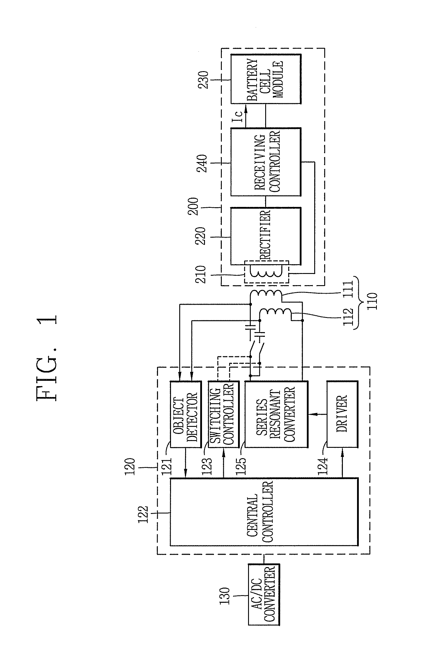
[0036]FIG. 1 is a block diagram that schematically shows a wireless power communication system in accordance with an exemplary embodiment. As shown, the wireless power communication system in accordance with an exemplary embodiment ...


PUM

PropertyMeasurementUnit
voltageaaaaaaaaaa
voltageaaaaaaaaaa
poweraaaaaaaaaa

Abstract

A wireless power transmitting device for a wireless power communication system. The wireless power transmitting device includes: a circuit board including an insulating layer and a ground formed on the insulating layer; a core of a magnetic substance disposed on the circuit board to have a concave portion; a wire-wound coil accommodated in the concave portion to have one end for receiving a power through the circuit board and the other end connected to the ground; and a metal layer disposed between the core and the insulating layer to be connected to the ground.

Description

CROSS-REFERENCE TO RELATED APPLICATION[0001]This application claims the benefit of Korean Patent Application No. 10-2011-0069708, filed on Jul. 14, 2011 in the Korean Intellectual Property Office, the disclosure of which is incorporated herein by reference.BACKGROUND OF THE INVENTION[0002]1. Field of the Invention[0003]The following description relates to a wireless power transmitting device used for a wireless power communication system.[0004]2. Description of the Related Art[0005]Generally, a rechargeable secondary battery is mounted on portable electronic devices such as a mobile communication terminal and Personal Digital Assistants (PDA). An individual charging device for supplying electric energy to a battery of a portable electronic device using commercial home power sources is required for charging the battery.[0006]The charging device and the battery usually include an external contact terminal, respectively. The charging device and the battery are electrically connected by...

Claims


Application Information

Patent Timeline
Patent Type & Authority Patents(United States)
IPC IPC(8): H01F27/42H01F37/00H01F38/00H04B5/00H02J5/00
CPCH04B5/0037H02J5/005H04B5/0087H02J7/0029H02J50/402H02J50/80H02J50/12H02J50/70H02J50/40H01F1/16H02J50/005
Inventor JUNG, CHUN-KILKUK, YOON-SANG
Owner GE HYBRID TECH
Why Eureka
Try Eureka