Aircraft environmental impact measurement system

a measurement system and aircraft technology, applied in the field of aircraft emissions, can solve the problems of difficult participation of the airline industry in any proposed international cap and trade program, high monetary value of so-called “carbon credits” and carbon footprint, and achieve the effect of improving the overall environmental performance and real-time environmental impact of aircra

Active Publication Date: 2016-02-23
HONEYWELL INT INC
View PDF29 Cites 20 Cited by
  • Summary
  • Abstract
  • Description
  • Claims
  • Application Information

AI Technical Summary

Benefits of technology

[0037]The display device 124 additionally renders recommendations 622 for improving the real-time environmental impact of the aircraft. These recommendations 622, at least in the depicted embodiment, include both textual and graphical recommendations. For example, the display device 124 renders textual recommendations that the flight crew should increase the power output of both engines, and should turn on the APU and increase its power to 40%. The graphical recommendations may mirror some or all of the textual recommendations 622. For example, the Engine #1 Performance field 602, Engine #2 Performance field 604, and APU field 606 are each rendered with dotted lines indicating how much the power output should be raised to meet the textual recommendations. In addition, the Altitude field 614 has a down arrow rendered next to the current altitude, indicating that lowering the current altitude below 32,000 feet could improve overall environmental performance.

Problems solved by technology

Moreover, the monetary value of so-called “carbon credits” and carbon footprint is high.
Presently, however, there is no common system or method for implementing these functions.
Thus, it may be difficult for the airline industry to participate in any proposed international cap and trade programs.

Method used


Image

  • Aircraft environmental impact measurement system
  • Aircraft environmental impact measurement system
  • Aircraft environmental impact measurement system

Examples


Embodiment Construction

[0015]The following detailed description is merely exemplary in nature and is not intended to limit the invention or the application and uses of the invention. As used herein, the word “exemplary” means “serving as an example, instance, or illustration.” Thus, any embodiment described herein as “exemplary” is not necessarily to be construed as preferred or advantageous over other embodiments. All of the embodiments described herein are exemplary embodiments provided to enable persons skilled in the art to make or use the invention and not to limit the scope of the invention which is defined by the claims. Furthermore, there is no intention to be bound by any expressed or implied theory presented in the preceding technical field, background, brief summary, or the following detailed description.

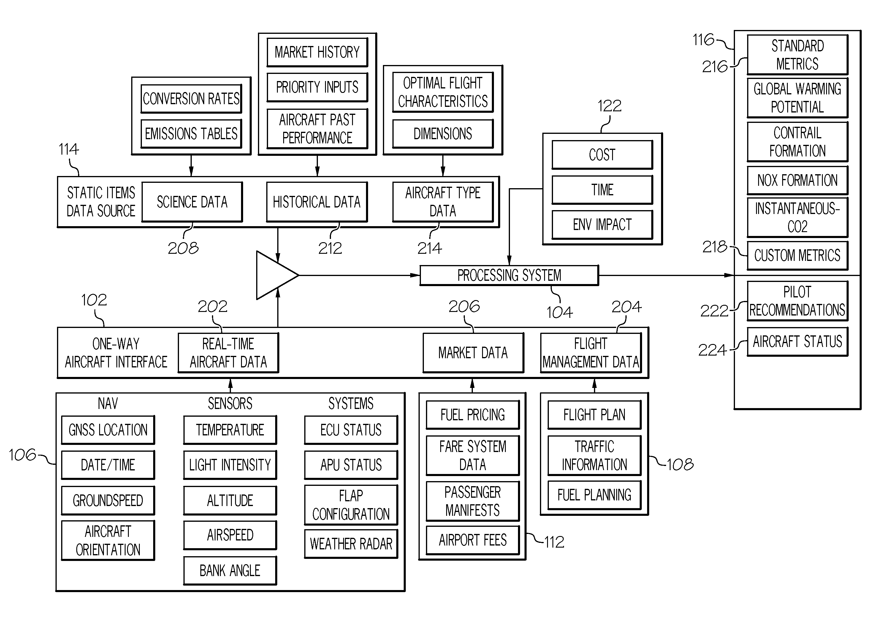
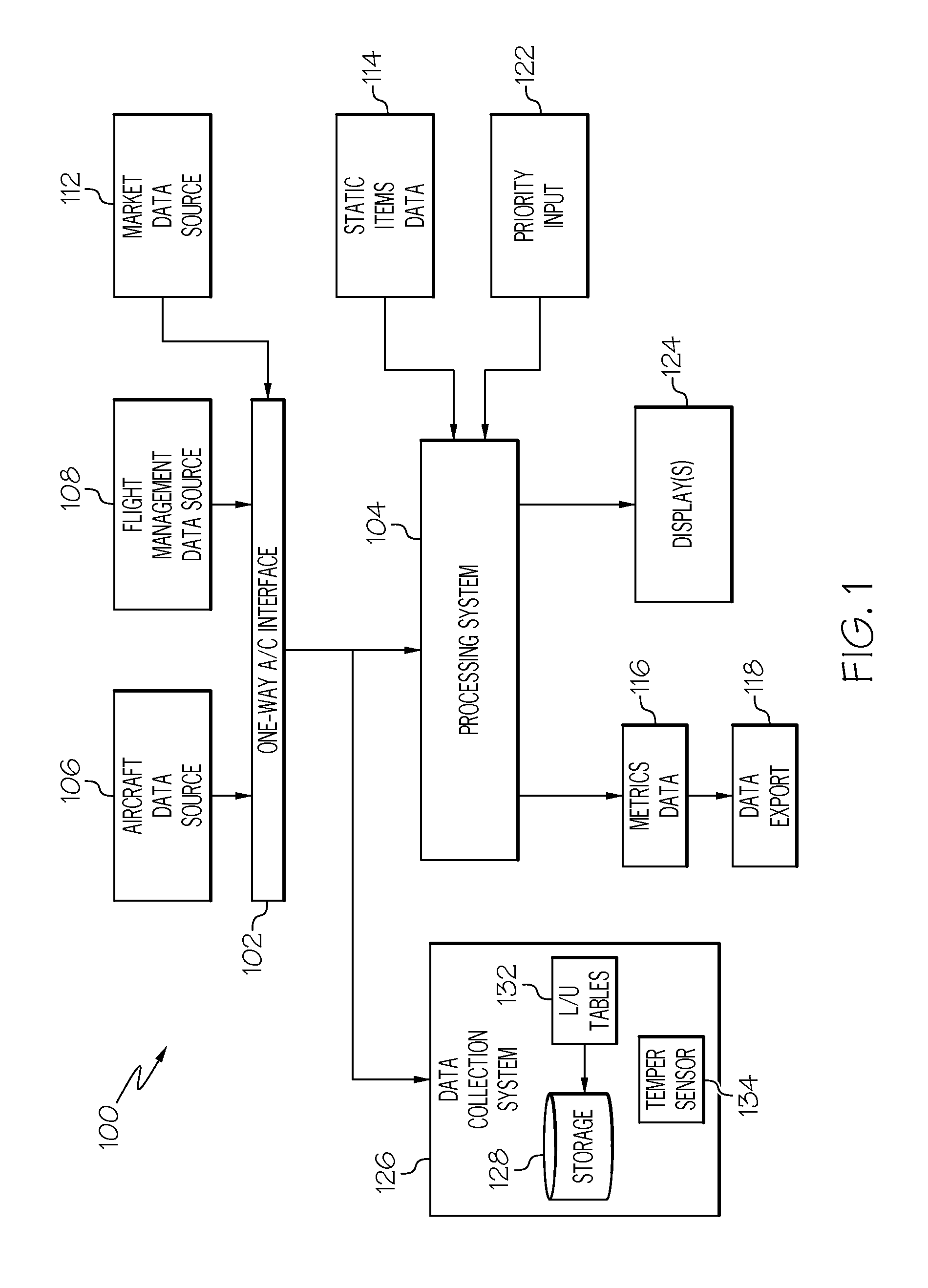
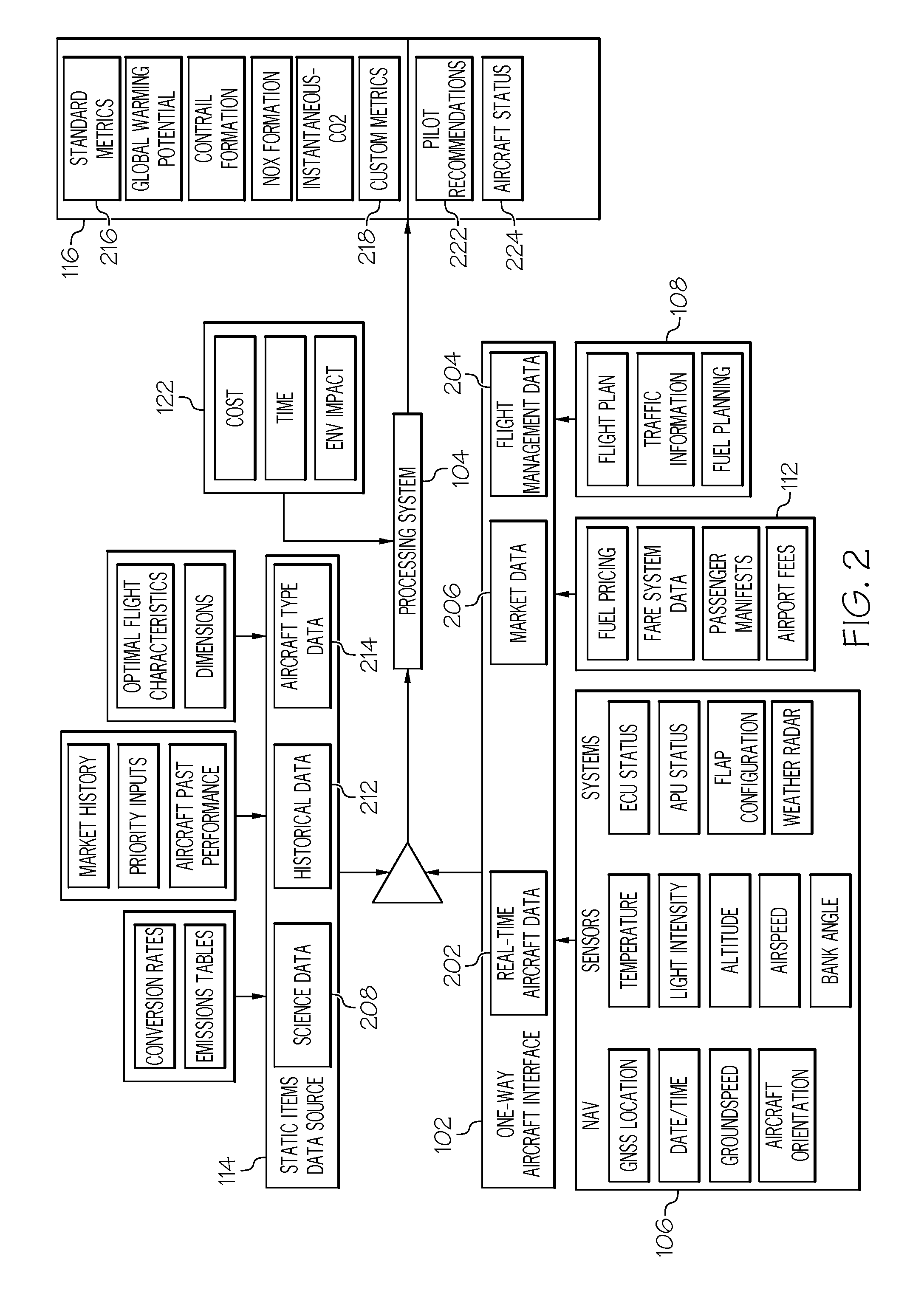
[0016]Referring first to FIG. 1, a functional block diagram of an aircraft environmental impact assessment system 100 is depicted and includes a one-way data interface 102 and a processing syst...


PUM


Abstract

An environmental impact measurement system for an aircraft includes a one-way data interface and a processing system. The one-way data interface is adapted to continuously receive and transmit aircraft data and flight plan data. The processing system is in operable communication with the one-way data interface to receive the aircraft data and the flight plan data transmitted therefrom. The processing system is configured, upon receipt of the aircraft data and the flight plan data, to generate at least data representative of real-time environmental impact of the aircraft, and recommendations for improving the real-time environmental impact of the aircraft.

Description

TECHNICAL FIELD[0001]The present invention generally relates to aircraft emissions, and more particularly relates to systems and methods for measuring the environmental impact of an aircraft.BACKGROUND[0002]Regardless of one's viewpoint, the issue of climate change is, and will likely remain, a primary concern to many legislative bodies and regulatory agencies worldwide. Indeed, various carbon emission restrictions have been, are being, or will be, enacted around the globe (e.g., cap-and-trade). As a result, tools for assessing and managing the carbon footprint of, for example, aircraft is a rapidly emerging need.[0003]In particular, airlines and air crews need a way to measure carbon emissions and environmental impact of their aircraft in different airspaces. Airlines and air crews also need a way to receive feedback regarding their real-time carbon footprint so that this data may be used to plan and optimize their operations, while at the same time balancing cost and flight schedu...

Claims


Application Information

Patent Timeline
Patent Type & Authority Patents(United States)
IPC IPC(8): G07C5/08G06Q30/02G08G5/00
CPCG07C5/0808G07C5/0841G08G5/0052G07C5/0825G06Q30/0201G06Q10/04G08G5/0021G06Q50/30
Inventor LAMKIN, ANDREW FANNONWARPINSKI, MATTHEWBUSTER, DUKENUTARO, JOSEPH J.
Owner HONEYWELL INT INC
Why Eureka
Try Eureka