Methods for objectively determining the visual axis of the eye and measuring its refraction

a technology of objective determination and eye, applied in the field of ophthalmic examination instruments, can solve the problems of no disclosure of how a new analysis pupil is determined nor how, and difficulty in integrating data from separate instruments,

Inactive Publication Date: 2016-03-01
WAKIL JOE S +3
View PDF2 Cites 0 Cited by
  • Summary
  • Abstract
  • Description
  • Claims
  • Application Information

AI Technical Summary

Benefits of technology

[0015]Other and further aspects, features, and advantages of the present invention will be apparent from the following description of the presently preferred embodiments of the invention given for the purpose of disclosure.

Problems solved by technology

Having different reference axes in corneal topography, in optical coherence tomography, in aberrometry, in refractometry, etc., caused difficulties when trying to integrate the data from separate instruments.
The cause of such statistics was the usage of an incorrect reference axis when performing the surgery.
However, there is no disclosure on how a new, analysis pupil is determined nor how the point of corneal intersection is found.
A drawback of this approach is in the uncertainty of its subjective procedure.
Subjective judgement is difficult because it is impossible for both points to be in focus for the patient.
Particularly, the prior art is deficient in methods for objectively determining the axis of best vision of the eye.

Method used


Image

  • Methods for objectively determining the visual axis of the eye and measuring its refraction
  • Methods for objectively determining the visual axis of the eye and measuring its refraction
  • Methods for objectively determining the visual axis of the eye and measuring its refraction

Examples


Embodiment Construction

[0027]As used herein in the specification, “a” or “an” may mean one or more. As used herein in the claim(s), when used in conjunction with the word “comprising”, the words “a” or “an” may mean one or more than one.

[0028]As used herein “another” or “other” may mean at least a second or more of the same or different claim element or components thereof. Similarly, the word “or” is intended to include “and” unless the context clearly indicates otherwise. “Comprise” means “include.”

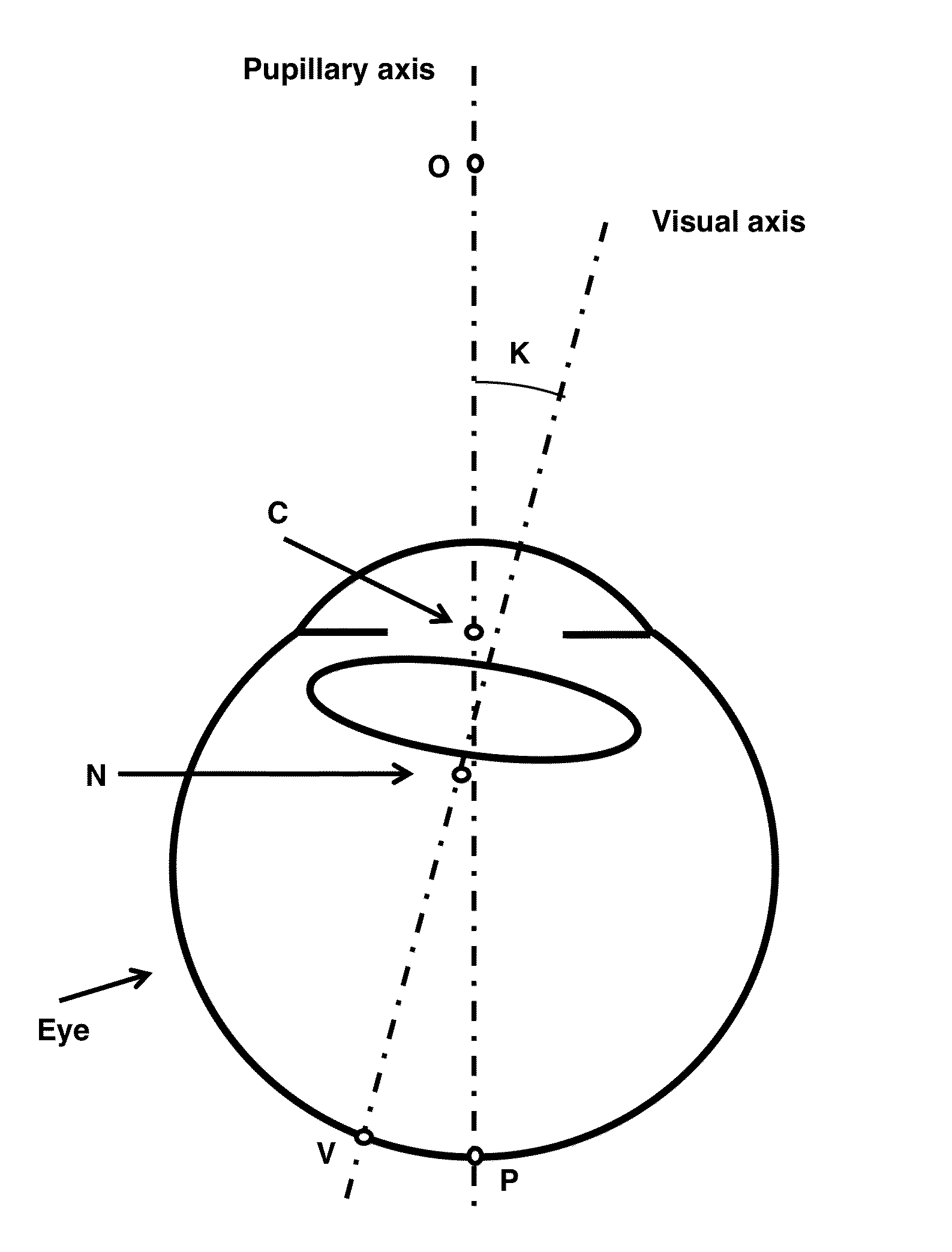
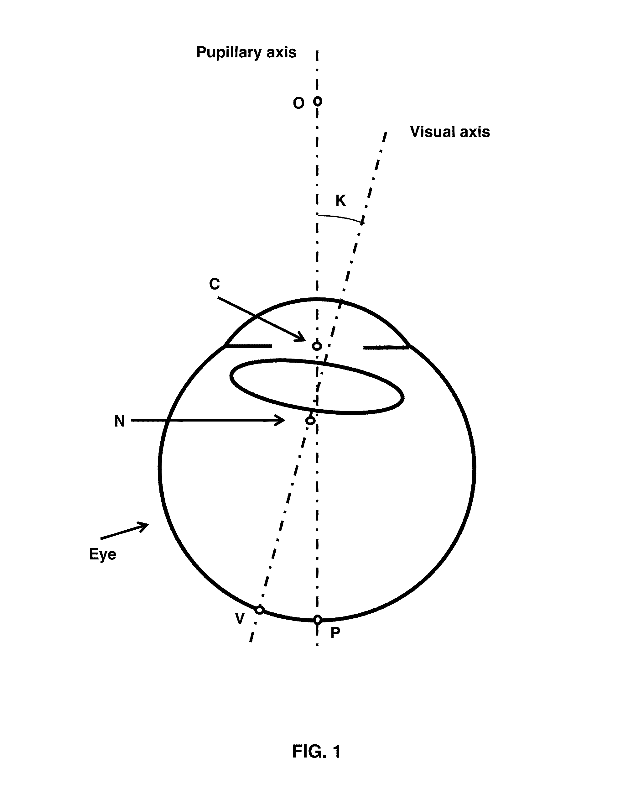
[0029]As used herein, “papillary axis” refers to the perpendicular to the anterior corneal surface and crosses the center of the pupil.

[0030]As used herein, “line of sight” refers to the connection between the point target, to which the eye is oriented, and the center of the pupil.

[0031]As used herein, “visual axis” refers to an axis that also is directed on the point target crossing it, but inside the eye. The visual axis crosses the first nodal point, not the center of the pupil.

[0032]As used herein, “Purkin...


PUM


Abstract

Provided are methods for determining an axis of best vision of an eye or for objectively determining a visual axis of an eye and for making the most accurate measurement of refraction. Generally, an optical measuring device or instrument projects laser beams into the eye during a scan. Positions of the projected beams are detected and measured on the retina to produce a set of projections. Wave front tilt of radiation that is backscattered from the retina is calculated as a best fit from the set of projections. The axis of best vision or the visual axis is reconstructed from a set of those traces of chief rays exiting from the eye that cross the nodal point of the optical system of the eye and that are normal to the wave front tilts. Measuring with the Styles Crawford scans centered over this axis provides the most accurate objective refraction.

Description

CROSS-REFERENCE TO RELATED APPLICATIONS[0001]This application is a nonprovisional under 35 U.S.C. §119(e) of provisional application U.S. Ser. No. 61 / 735,412, filed Dec. 10, 2012, now abandoned, the entirety of which is hereby incorporated by reference.BACKGROUND OF THE INVENTION[0002]1. Field of the Invention[0003]The present invention relates generally to the fields of ophthalmic instruments that are used to examine the eye. More specifically, the present invention relates to ophthalmic examination instruments that measure and characterize the properties of the eye with high accuracy of their localization.[0004]2. Description of the Related Art[0005]The eye is not an ideal optical system and, therefore, different reference axes can be used to describe its properties in a 3D space. These properties cannot be comparable unless they are calculated with respect to the same reference axis. Four axes are used: optical axis, pupillary axis, line of sight, and visual axis. Similarly to th...

Claims


Application Information

Patent Timeline
Patent Type & Authority Patents(United States)
IPC IPC(8): A61B3/14A61B3/10A61B3/107A61B3/00A61B3/103
CPCA61B3/107A61B3/1015A61B3/0025A61B3/103A61B3/028
Inventor WAKIL, JOE, S.VAN, SAARLOOS, PAULMOLEBNY, VASYLMOLEBNY, SERGIY
Owner WAKIL JOE S
Why Eureka
Try Eureka