Biosleeve human-machine interface

a technology of human-machine interface and biosleeve, which is applied in the field of human-machine interface, can solve the problems that the current means of unmanned control of military platforms are not soldier-centric or responsive to the needs of field personnel

Active Publication Date: 2016-03-08
CALIFORNIA INST OF TECH
View PDF2 Cites 69 Cited by
  • Summary
  • Abstract
  • Description
  • Claims
  • Application Information

AI Technical Summary

Problems solved by technology

The current means of unmanned controlling military platforms are not soldier-centric or responsive to the needs of the field personnel.
Any considered robotic military platform should enhance and not inhibit mission performance due to inefficient means of control.

Method used


Image

  • Biosleeve human-machine interface
  • Biosleeve human-machine interface
  • Biosleeve human-machine interface

Examples


Embodiment Construction

1. Overview

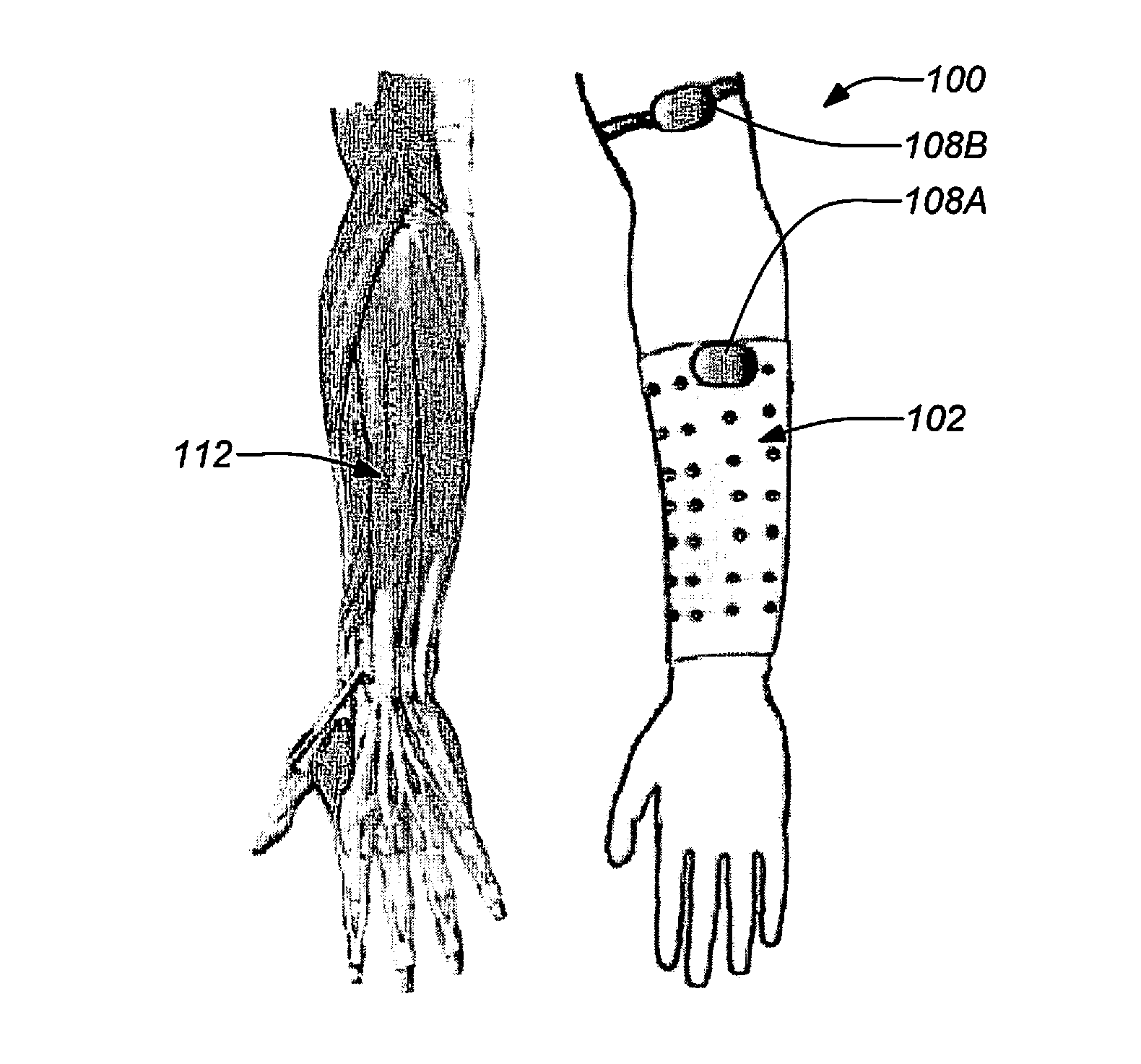
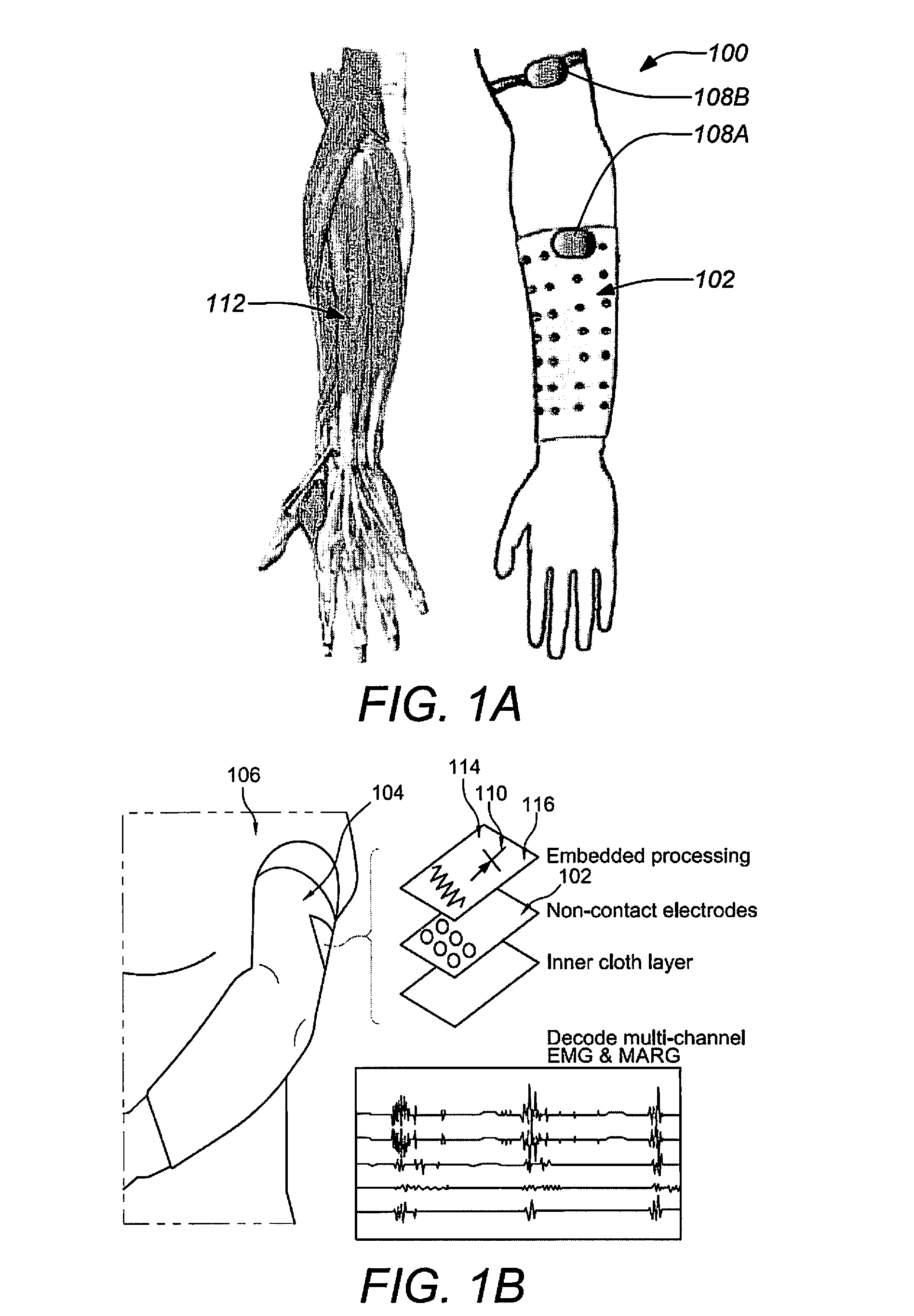
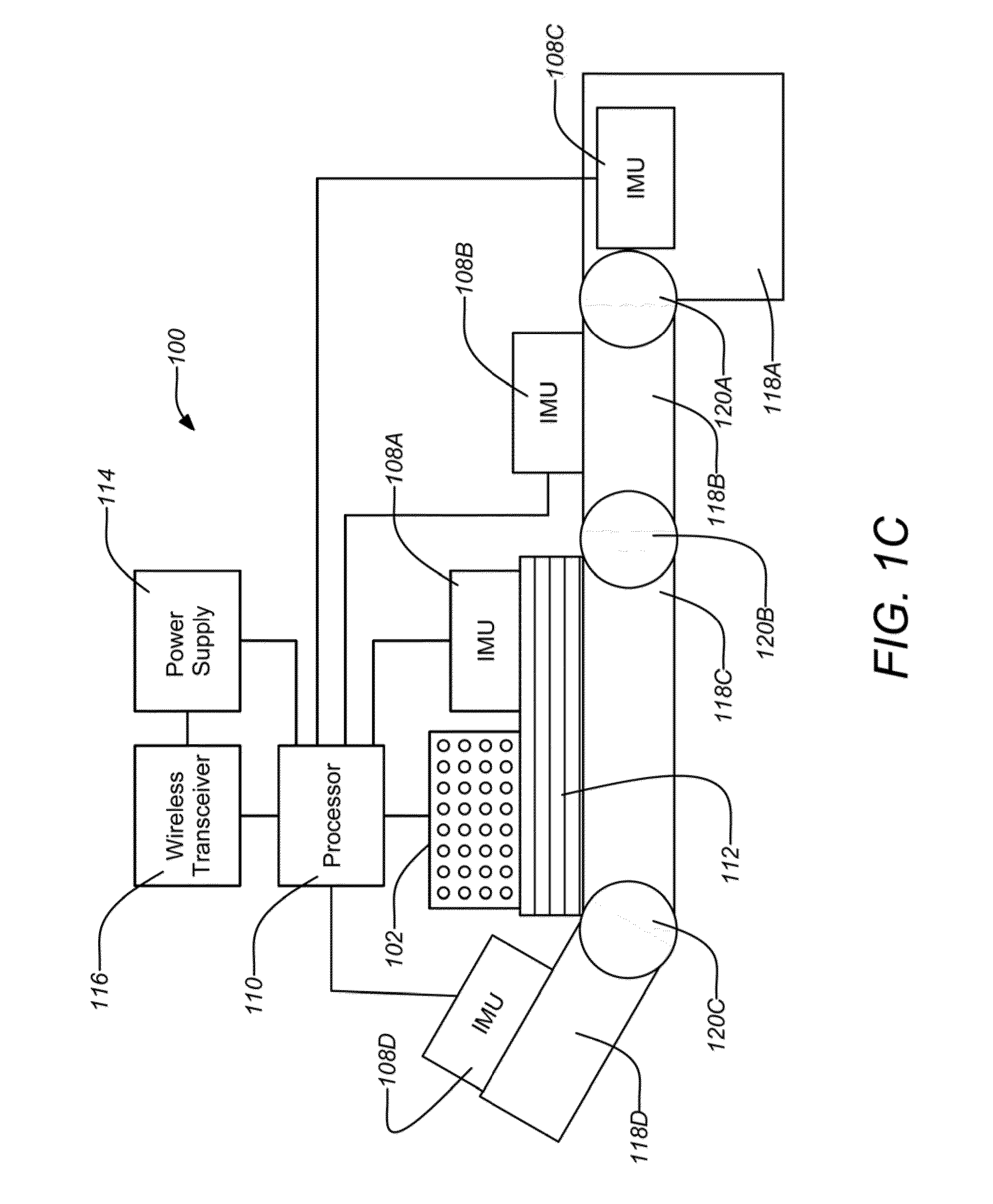
[0028]Embodiments of the invention may be targeted at using bio-signal inputs to set navigation and manipulation goals for a robot (e.g., simply by pointing). An example system embodiment may comprise an electromyography (EMG) “BioSleeve”, having a high density sensor array for robust, practical signal collection from forearm muscles. Significantly, the EMG sensor array data may then be fused with inertial measurement unit (IMU) data to provide enhanced detection of user hand and arm motion.

[0029]Embodiments of the invention can be employed to decode robot commands from the EMG and IMU data having up to sixteen bipolar surface EMG sensors in one example. The BioSleeve can be employed in the recognition of static hand positions (e.g. palm facing front, fingers upwards) and dynamic gestures (e.g. hand wave). Embodiments of the invention can achieve over 90% correct recognition in five static and nine dynamic gestures. A BioSleeve embodiment of the invention may be used to c...


PUM


Abstract

Systems and methods for sensing human muscle action and gestures in order to control machines or robotic devices are disclosed. One exemplary system employs a tight fitting sleeve worn on a user arm and including a plurality of electromyography (EMG) sensors and at least one inertial measurement unit (IMU). Power, signal processing, and communications electronics may be built into the sleeve and control data may be transmitted wirelessly to the controlled machine or robotic device.

Description

CROSS-REFERENCE TO RELATED APPLICATIONS[0001]This application claims the benefit under 35 U.S.C. §119(e) of the following U.S. provisional patent applications, which are incorporated by reference herein:[0002]U.S. Provisional Patent Application No. 61 / 651,728, filed May 25, 2012, and entitled “BioSleeve Human-Machine Interface”, by Christopher Assad.STATEMENT OF GOVERNMENT RIGHTS[0003]The invention described herein was made in the performance of work under a NASA contract, and is subject to the provisions of Public Law 96-517 (35 USC 202) in which the Contractor has elected to retain title.BACKGROUND OF THE INVENTION[0004]1. Field of the Invention[0005]This invention relates to human-machine interfaces. Particularly, this invention relates to human-machine interfaces to control robotic devices.[0006]2. Description of the Related Art[0007]Fundamental to the existence of robotic devices is the requirement for interfaces to facilitate human control of those devices. Robotic devices may...

Claims


Application Information

Patent Timeline
Patent Type & Authority Patents(United States)
IPC IPC(8): B25J9/16G06F3/01B25J9/10G06K9/00A61B5/00A61B5/11A61B5/0488
CPCB25J9/1694A61B5/04888B25J9/104G06F3/011G06F3/014A61B5/1116A61B5/1122A61B5/6825A61B5/6826A61B5/6831A61B5/721A61B5/7267G05B2219/36435G06K9/00355G06F3/015A61B5/389G06F3/017G06V40/28
Inventor ASSAD, CHRISTOPHER
Owner CALIFORNIA INST OF TECH
Why Eureka
Try Eureka