Vehicle

a technology for vehicles and hulls, applied in the field of vehicles, can solve the problems of large amount of energy waste, unstable vehicle travel, and reduced tire-road adhesion, and achieve the effects of reducing the lifting force, and reducing the amount of energy was

Active Publication Date: 2016-03-08
ZHU XIAOYI
View PDF6 Cites 5 Cited by
  • Summary
  • Abstract
  • Description
  • Claims
  • Application Information

AI Technical Summary

Benefits of technology

[0007]To achieve the above objective, in accordance with one embodiment of the invention, there is provided a vehicle that comprises a housing. The housing comprises an outer portion, an inner portion, an air-flow channel, a plurality of air inlets, an air outlet, and a spoiler surface or a spoiler. The air-flow channel is disposed between the outer portion and the inner portion of the housing. The air inlets are disposed on the outer portion of the housing, and the air outlet is disposed at a rear of the outer portion of the housing. The air-flow channel communicates with the air inlets and the air outlet. The spoiler surface or the spoiler is disposed on a bottom of the outer portion of the housing, a top of the inner portion of the housing, or both the bottom of the outer portion and the top of the inner portion of the housing, for extending path of the air, whereby producing lifting force of the inner portion of the housing and eliminating lifting force of the outer portion of the housing during the travelling of the vehicle.
[0014]In accordance with another embodiment of the invention, there is provided a vehicle comprising a housing. The housing comprising an upper portion, a bottom, and an air-flow channel. The air-flow channel is disposed between the upper portion and the bottom of the housing and communicates with the atmosphere. A lower surface of the bottom of the housing and / or the upper surface of the upper portion of the housing are provided with spoiler or spoiler surface for extending path of the air, whereby producing lifting force of the upper portion of the housing and eliminating lifting force of the bottom of the housing during the travelling of the vehicle.
[0018]1. The upper part of the inner portion of the housing is in the shape of the arc so that the air-flow path therein is longer than the air-flow path of the lower part thereof, thereby producing the lifting force; and meanwhile, the air-flow path at the lower part of the outer portion of the housing is longer than that at the upper part thereof, thereby eliminating the lifting force. The inner portion of the housing is the whole carrying space that suspends within the air-flow channel between in the inner and the outer portions of the housing. The lifting force produced on the inner portion of the housing overcomes or partially overcomes the downward gravity produced by the self-weight of the vehicle, therefore, the vehicle is energy-saving as the downward force on the vehicle is decreased during the travelling and is much safer as the lifting force is eliminated by the outer portion of the housing and the tire-road adhesion is enlarged.
[0019]2. The inner portion of the housing produces the lifting force while the outer portion of the housing eliminates the lifting force. These structures that seem to be contradicted are reasonably integrated. The production of the lifting force by the inner portion will not drive the outer portion to produce the lifting force. On the contrary, the inner portion is suspended in the air-flow channel, and the outer portion eliminates the lifting force and increases the tire-road adhesion. Meanwhile, the carrying space of the inner portion decreases the self-weight, so that vehicle is much energy-saving and safe travelling.

Problems solved by technology

During the travel of conventional vehicles, a lifting force is produced because the air-flow path on the upper portion is longer than the air-flow path on the lower portion, and thus, the tire-road adhesion is decreased, resulting in an unstable travelling of the vehicles.
However, this method leads to a large amount of energy waste.

Method used


Image

  • Vehicle
  • Vehicle
  • Vehicle

Examples


example 1

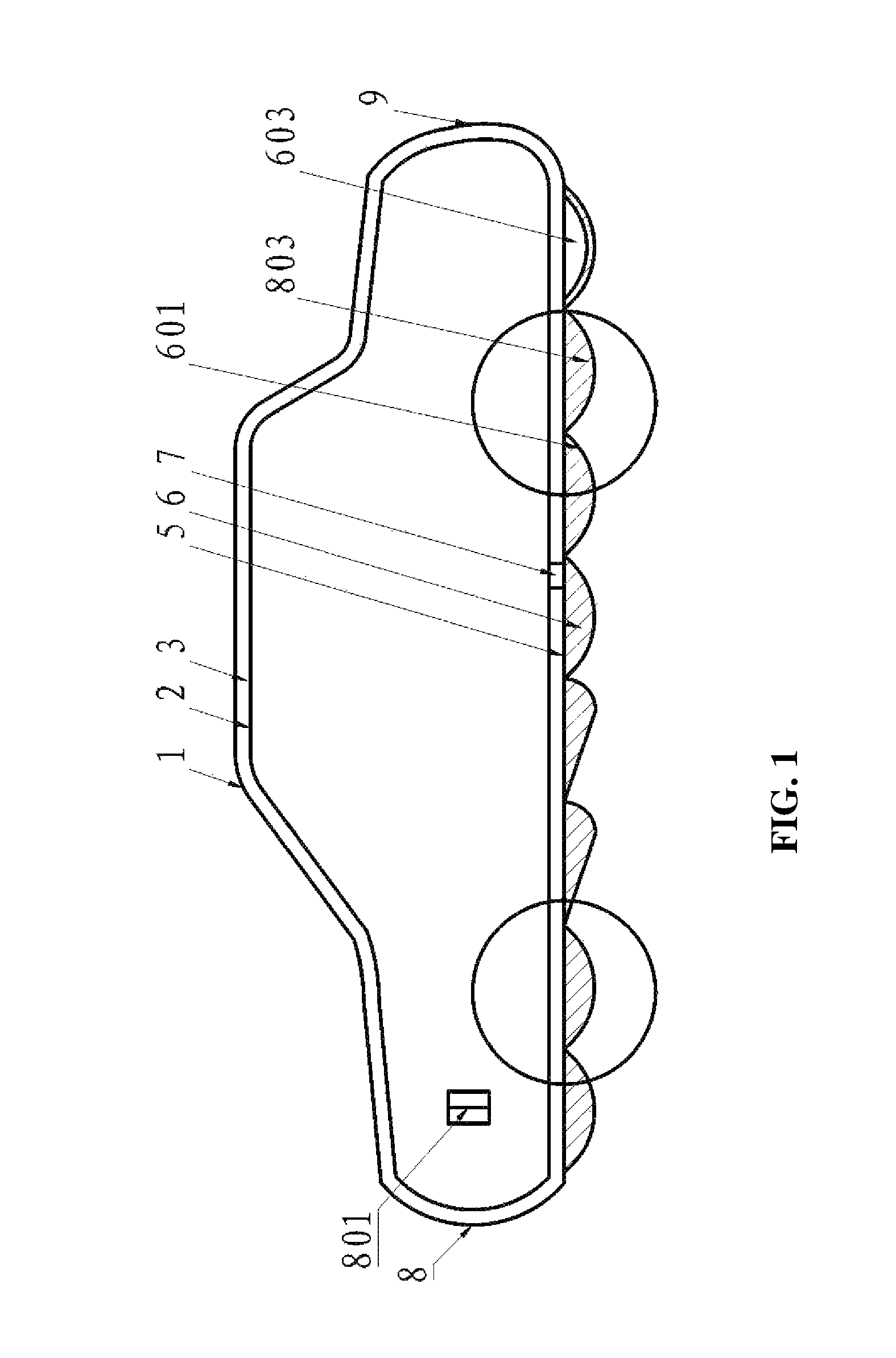
[0029]As shown in FIG. 1, an energy saving vehicle comprises a housing comprising an outer portion 1 and an inner portion 2. An air-flow channel 3 is disposed between the inner portion 2 and the outer portion 1 of the housing. The air-flow channel 3 communicates with an air outlet 9 arranged on a rear of the outer portion of the housing via a first air inlet 8 arranged on a front of the outer portion and a plurality of second air inlets 801 arranged on a periphery of the outer portion of the housing. A plurality of elastic devices 7 connected to one another are arranged between or around a bottom 5 of the housing and the inner portion 2 of the housing for reducing the vibration occurring in the travelling of the vehicle. Particularly, the inner portion of the housing comprises a curved upper surface and a flat lower surface, a lifting force is consequently resulted during the travelling of the vehicle; and the flexible connection of the elastic devices 7 functions in avoiding or att...

example 2

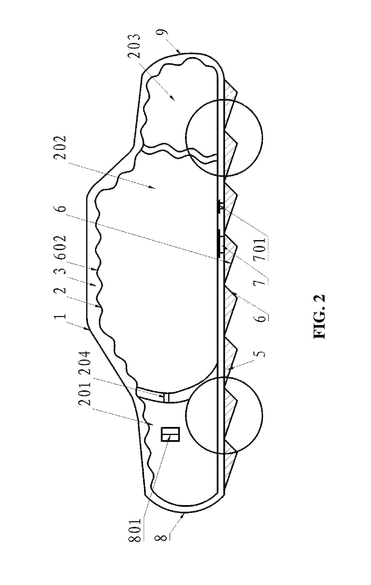
[0041]As shown in FIG. 2, the vehicle is the same as that in Example 1 except that the air-flow channel 3 communicating with the atmosphere via the first and the second air inlets 8, 801 divides the inner portion 2 of the housing into a first carrying cabin 201, a second carrying cabin 202, and a third carrying cabin 203. The carrying cabins are connected to one another via connecting pieces 204. When the vehicle travels, the air-flow channel 3 surrounds each carrying cabin, as each of the carrying cabins has a curved upper surface and a flat lower surface, the path of the air passing through the curved upper surface is different from that through the lower surface, resulting in a pressure difference and further producing a lifting force on each carrying cabin, and thus, a larger lifting force is produced under an overall action of the three carrying cabins 201, 202, and 203. The spoiler surface 6 can also be formed by a plurality of triangles.

[0042]The upper surface of each of the ...

example 3

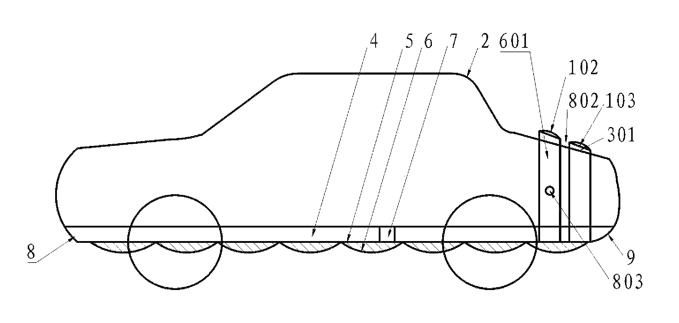
[0046]As shown in FIG. 3, the vehicle is the same as that in Example 2 except that the outer portion 1 of the housing of the vehicle comprises a plurality of independent spoilers 601 arranged on surfaces of the upper and the lateral of the vehicle according to the profile of the vehicle. A lower part of the spoiler 601 is connected to the bottom 5 of the housing. An open air-flow channel 4 is formed between the inner portion 2 and the bottom 5 of the housing, and the open air-flow channel 4 communicates with the first air inlet 8 and the air outlet 9. The spoiler comprises a curved upper surface 102 and a flat inner surface 103. An additional air-flow channel 301 is formed between the flat inner surfaces 103 of the spoiler and the inner portion 2 of the housing. Pressure ports are formed between two adjacent spoilers and enable the additional air-flow channel 301 to communicate with the atmosphere.

[0047]In travelling of the vehicle, the air flows into the open air-flow channel 4 via...


PUM


Abstract

A vehicle including a housing. The housing includes an outer portion, an inner portion, an air-flow channel, a plurality of air inlets, an air outlet, and a spoiler surface or a spoiler. The air-flow channel is disposed between the outer portion and the inner portion of the housing. The air inlets are disposed on the outer portion of the housing, and the air outlet is disposed at a rear of the outer portion of the housing. The air-flow channel communicates with the air inlets and the air outlet. The spoiler surface or the spoiler is disposed on a bottom of the outer portion of the housing, a top of the inner portion of the housing, or both the bottom of the outer portion and the top of the inner portion of the housing, for extending path of the air.

Description

CROSS-REFERENCE TO RELATED APPLICATIONS[0001]This application is a continuation-in-part of U.S. application Ser. No. 13 / 786,413 filed Mar. 5, 2013, now pending, which is a divisional of U.S. Ser. No. 13 / 335,913 filed on Dec. 22, 2011, issued as U.S. Pat. No. 8,408,635 on Apr. 2, 2013, which is a divisional of U.S. Ser. No. 12 / 559,543 filed on Sep. 15, 2009, issued as U.S. Pat. No. 8,113,569 on Feb. 14, 2012, which is a continuation in part of International Patent Application No. PCT / CN2008 / 073367, with an international filing date of Dec. 8, 2008, designating the United States. This application also claims foreign priority benefits to Chinese Patent Application No. 200710186155.9, filed Dec. 27, 2007, Chinese Patent Application No. 200710186156.3, filed Dec. 27, 2007, Chinese Patent Application No. 200810000302.3, filed Jan. 7, 2008, Chinese Patent Application No. 200810008130.4, filed Feb. 13, 2008, and Chinese Patent Application No. 200810068379.4, filed Jul. 11, 2008. The content...

Claims


Application Information

Patent Timeline
Patent Type & Authority Patents(United States)
IPC IPC(8): B62D35/00B62D35/02
CPCB62D35/00B62D35/001B62D35/02Y02T70/121Y02T10/82Y02T10/88Y02T70/10
Inventor ZHU, XIAOYI
Owner ZHU XIAOYI
Why Eureka
Try Eureka