
Pressure medium system, in particular hydraulic system

a technology of pressure medium and hydraulic system, which is applied in the direction of fluid-pressure actuators, fluid-pressure actuator components, servometer circuits, etc., can solve the problems of pressure limitation, pressure limitation, and pressure limitation,

Inactive Publication Date: 2016-03-08
LUGWIG EHRHARDT GMBH
View PDF18 Cites 1 Cited by
  • Summary
  • Abstract
  • Description
  • Claims
  • Application Information

AI Technical Summary

Benefits of technology

This patent describes a method for controlling a fluid pump that reduces the amount of energy consumed and protects the pump from damage. It achieves this by allowing the pump to operate less frequently at higher pressures, and using a pressure-limiting valve to protect it from excess fluid pressure. The control unit is also able to quickly switch the pump back on when the fluid pressure is low to prevent a further drop. Overall, this method improves the efficiency and reliability of fluid pumps in a variety of situations.

Problems solved by technology

This pressure limitation can, for example, be required when the hydraulic pump, due to a malfunction, delivers a larger volumetric flow than is necessary for maintaining a predefined target value.
Furthermore, this pressure limitation can, however, also be required when the hydraulic oil enclosed in the hydraulic system expands due to heating, which is associated with a corresponding pressure rise.
This pressure limitation is, however, associated with a corresponding dissipation power of the pressure-limiting valve.
On the other hand, the hydraulic pump is mostly operated at a high hydraulic pressure near the target value, which is associated with a correspondingly high load of the hydraulic pump and with a correspondingly high energy expenditure.
Furthermore, there is the problem that the hydraulic pump must be turned on again when the hydraulic pressure has fallen below a predefined minimum pressure.
It is problematic in this case that the so-called subsequent switching of the hydraulic pump does not immediately lead to a pressure rise, which has various causes.
On the one hand, the motor relay of the hydraulic pump has a certain dead time, whereby the start-up of the hydraulic pump is delayed.
This temporal delay can cause for subsequent switching of the hydraulic pump that the predefined minimum pressure is fallen short of.

Method used


Image

  • Pressure medium system, in particular hydraulic system
  • Pressure medium system, in particular hydraulic system
  • Pressure medium system, in particular hydraulic system

Examples


Embodiment Construction

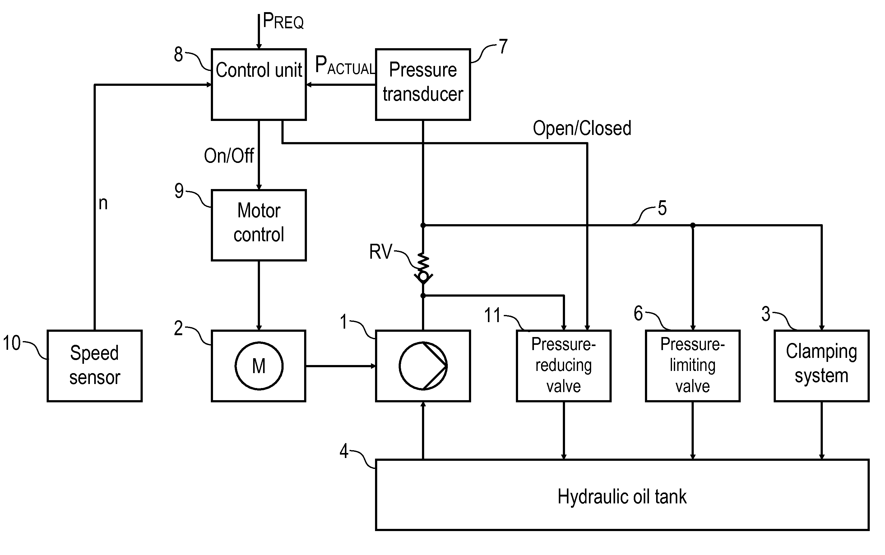
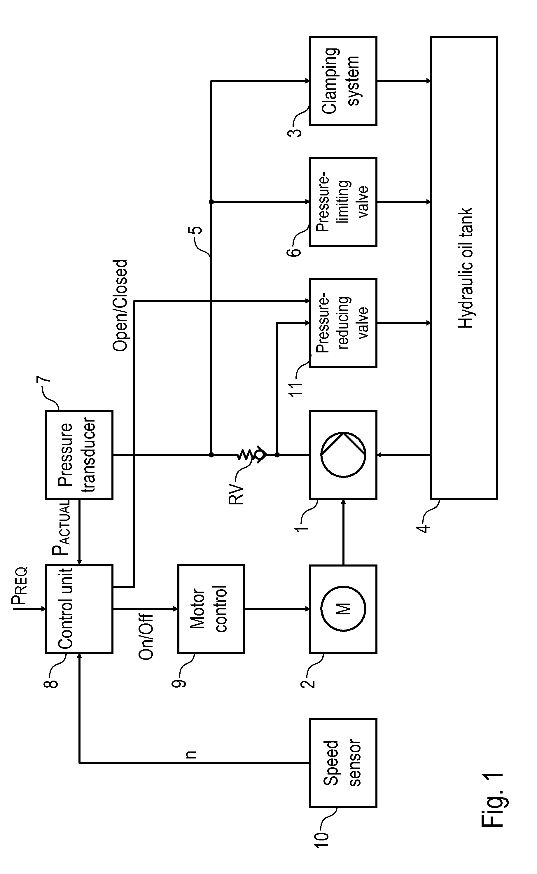
[0072]FIG. 1 shows a hydraulic system according to the invention having a hydraulic pump 1, which is driven by an electric motor 2, and supplies a mechanical clamping system 3 with the hydraulic pressure required for operation.

[0073]The hydraulic pump 1 is connected on the input side with a hydraulic oil tank 4 from which the hydraulic pump 1 extracts hydraulic oil and pumps via a back-pressure valve RV into a high-pressure area 5 to which the clamping system 3 is connected.

[0074]Furthermore, the hydraulic system has a pressure-limiting valve 6, which connects the high-pressure area 5 with the hydraulic oil tank 4. The pressure-limiting valve 6 is closed in the normal state and opens when the actual hydraulic pressure PACTUAL in the high-pressure area 5 exceeds a predefined maximum value PMAX.

[0075]Furthermore, the hydraulic system has a pressure sensor 7, which measures the actual hydraulic pressure PACTUAL in the high-pressure area 5 and transmits it to a control unit 8, which tri...


PUM


Abstract

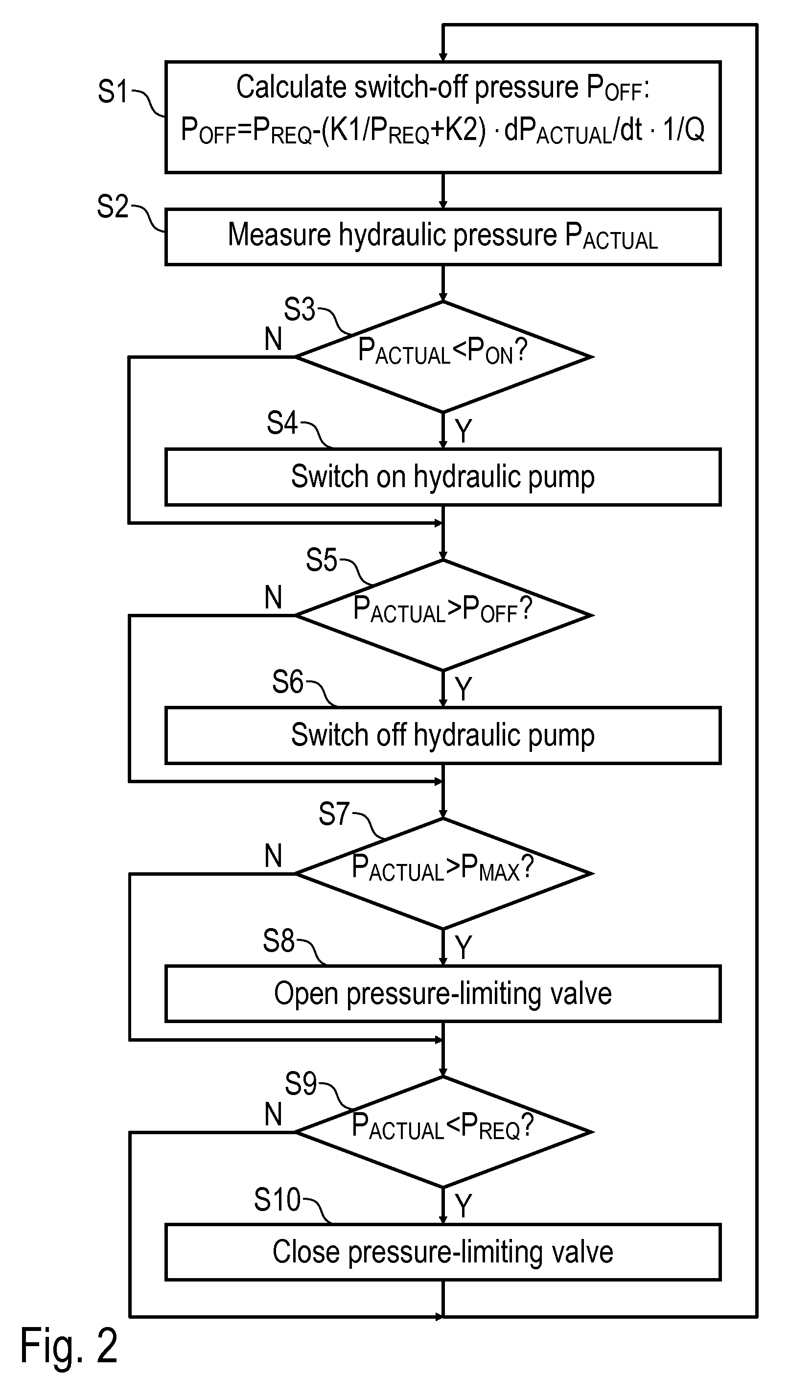
The invention relates to a pressure medium system, in particular a hydraulic system, having a fluid pump for delivering a drive fluid with a certain delivery flow rate and a certain fluid pressure, and having a control unit which switches the fluid pump on or off in order to set a predefined setpoint value of the fluid pressure, wherein the fluid pump exhibits an inertia-induced overrun when switched off, such that during the overrun of the fluid pump, the fluid pressure still rises while the fluid pump has already been switched off. It is proposed that, during the increase of the fluid pressure to the predefined setpoint value, the control unit switches the fluid pump off before the fluid pressure has reached the predefined setpoint value. The invention also includes a corresponding operating method.

Description

CROSS-REFERENCE TO RELATED APPLICATIONS[0001]This national stage application claims the benefit under 35 U.S.C. §371 of International Application No. PCT / EP2011 / 002598 filed on Jun. 20, 2012, entitled PRESSURE MEDIUM SYSTEM, IN PATRICULAT HYDRAULIC SYSTEM, which in turns takes its priority from German Patent Application No. 10 2011 112 701.5 filed Sep. 5, 2011 and German Patent Application No. 10 2011 105 584.7 filed Jun. 27, 2011, and all of whose entire disclosures are incorporated by reference herein.FIELD OF INVENTION[0002]The invention concerns a pressure medium system, in particular a hydraulic system of a clamping device for mechanical clamping of workpieces or workpiece holders, such as workpiece pallets.[0003]Such clamping devices having a hydraulic system are, for example, known from DE 31 36 177 A1 and contain a hydraulic pump, a pressure sensor and a pressure-limiting valve as well as a control unit.[0004]The hydraulic pump generates the hydraulic pressure required for o...

Claims


Application Information

Patent Timeline
Patent Type & Authority Patents(United States)
IPC IPC(8): F15B21/08
CPCF15B21/08F15B2211/20546F15B2211/251F15B2211/26
Inventor EHRHARDT, WINFRIEDWESTERHAGEN, GEORG
Owner LUGWIG EHRHARDT GMBH
Learn More