Secondary battery

a second-generation battery and battery technology, applied in the field of secondary batteries, can solve the problems of insufficient utilization of the merits of high-capacity anodes using alloy materials, insufficient suppression of expansion and shrinkage of anodes in charge and discharge, and insufficient utilization of cycle characteristics of high-capacity anodes, etc., to achieve sufficient capacity, charge and discharge cycle characteristics can be improved, and the load characteristics and discharge cycle characteristics can be deteriorated due to lithium precipitation

Active Publication Date: 2010-10-05
MURATA MFG CO LTD
View PDF16 Cites 7 Cited by
  • Summary
  • Abstract
  • Description
  • Claims
  • Application Information

AI Technical Summary

Benefits of technology

[0013]In the first secondary battery of the embodiment of the invention, the most inner circumferential portion of the cathode active material layer is provided in the region where the most inner circumferential portion does not overlap with the region where the lead is formed in the short axis direction of the cross section. Therefore, compared to the case that the cathode active material layer is provided in a region where the cathode active material layer overlaps with the lead in the short axis direction, pressure rise particularly in the region where the lead is formed due to expansion of the anode facing the cathode in the most inner circumference is eased. In the result, deviation of the pressure distribution inside the spirally wound electrode body is hardly caused.
[0015]The second secondary battery of the embodiment of the invention is structured as above. Therefore, compared to the case that the spirally winding center side end of the cathode active material layer and the spirally winding outer circumferential side end of the cathode active material layer are provided to overlap with each other in the short axis direction of the cross section, deviation of the pressure distribution inside the spirally wound electrode body due to expansion of the anode facing the cathode is hardly caused. The main reason thereof is that stress concentration in the vicinity of the end on the spirally winding center side and in the vicinity of the end on the spirally winding outer circumferential side in the cathode active material layer is relaxed.
[0016]According to the secondary battery of the embodiment of the invention, in the short axis direction of the cross section, the inner circumferential portion of the cathode active material layer and the lead do not overlap with each other, or the spirally winding center side end and the spirally winding outer circumferential side end of the cathode active material layer do not overlap with each other. Therefore, deviation of the pressure distribution inside the spirally wound electrode body can be prevented from being generated. In the result, deterioration of the load characteristics and the charge and discharge cycle characteristics due to precipitation of lithium can be prevented. Consequently, by using an alloy material as an anode active material, the sufficient capacity can be secured, and the charge and discharge cycle characteristics can be improved.

Problems solved by technology

However, even in the cases using the foregoing methods, it is difficult to sufficiently suppress expansion and shrinkage of the anode in charge and discharge.
Therefore, in the result, it is an actual situation that effects of improving cycle characteristics are not obtained, and merits of the high-capacity anode using the alloy material are not sufficiently utilized.
More specifically, for example, when an anode made of the foregoing alloy material is used for a spirally wound electrode body that is contained in a square battery in the shape of an approximate rectangular parallelepiped and its cross section perpendicular to the spirally winding axis is planular, the pressure distribution inside the spirally wound electrode body becomes uneven due to expansion according to charge and discharge.
In a portion with the high pressure, there is a possibility that a separator is compressed and thus slight short-circuit is generated.
In the result, there is a possibility that the load characteristics and the charge and discharge cycle characteristics are deteriorated.
Further, when the spirally wound electrode body is inserted in a battery can with the low rigidity, there is a possibility that the anode is expanded and thus the battery can is pressed from inside and deformed.

Method used


Image

  • Secondary battery
  • Secondary battery
  • Secondary battery

Examples


first embodiment

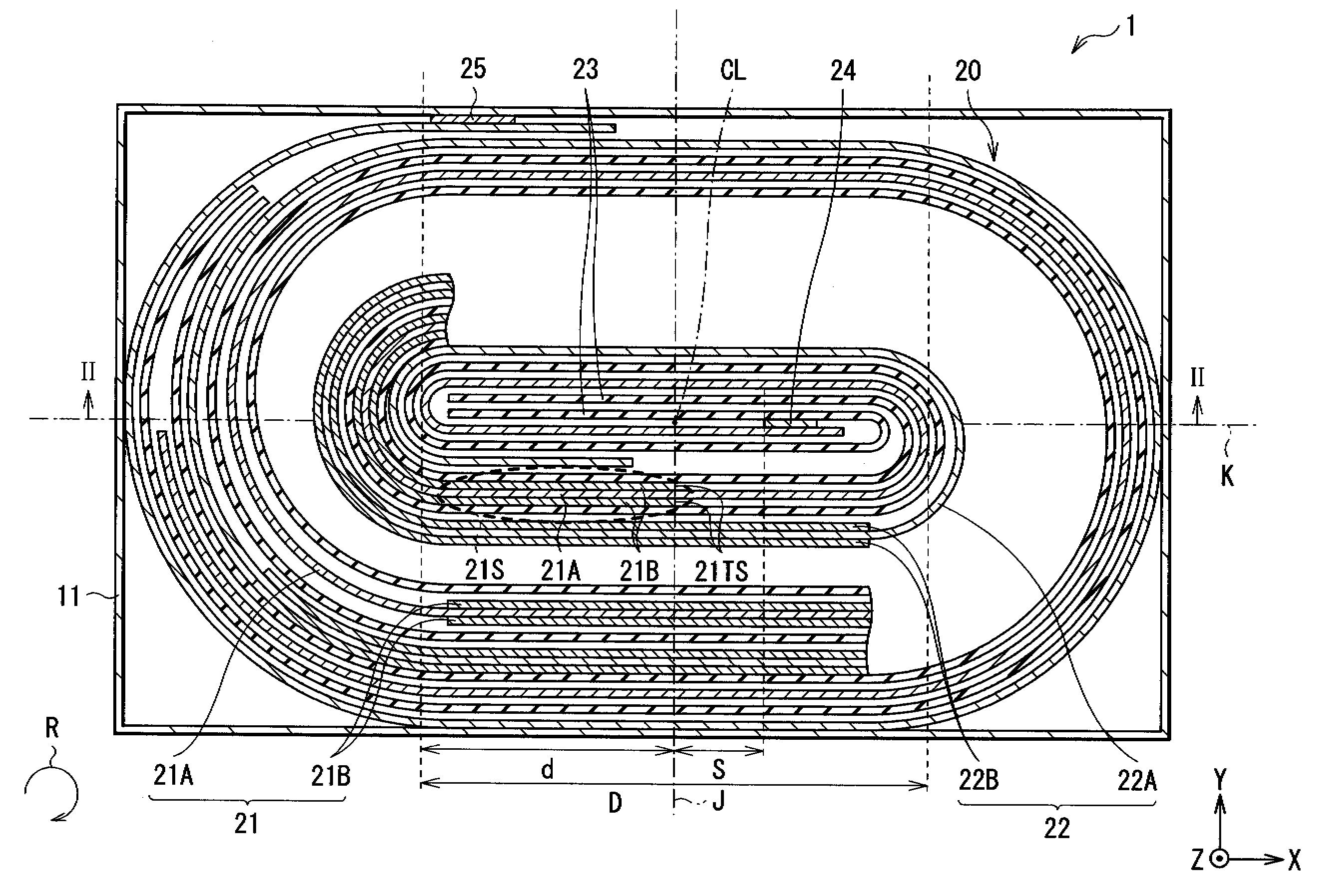
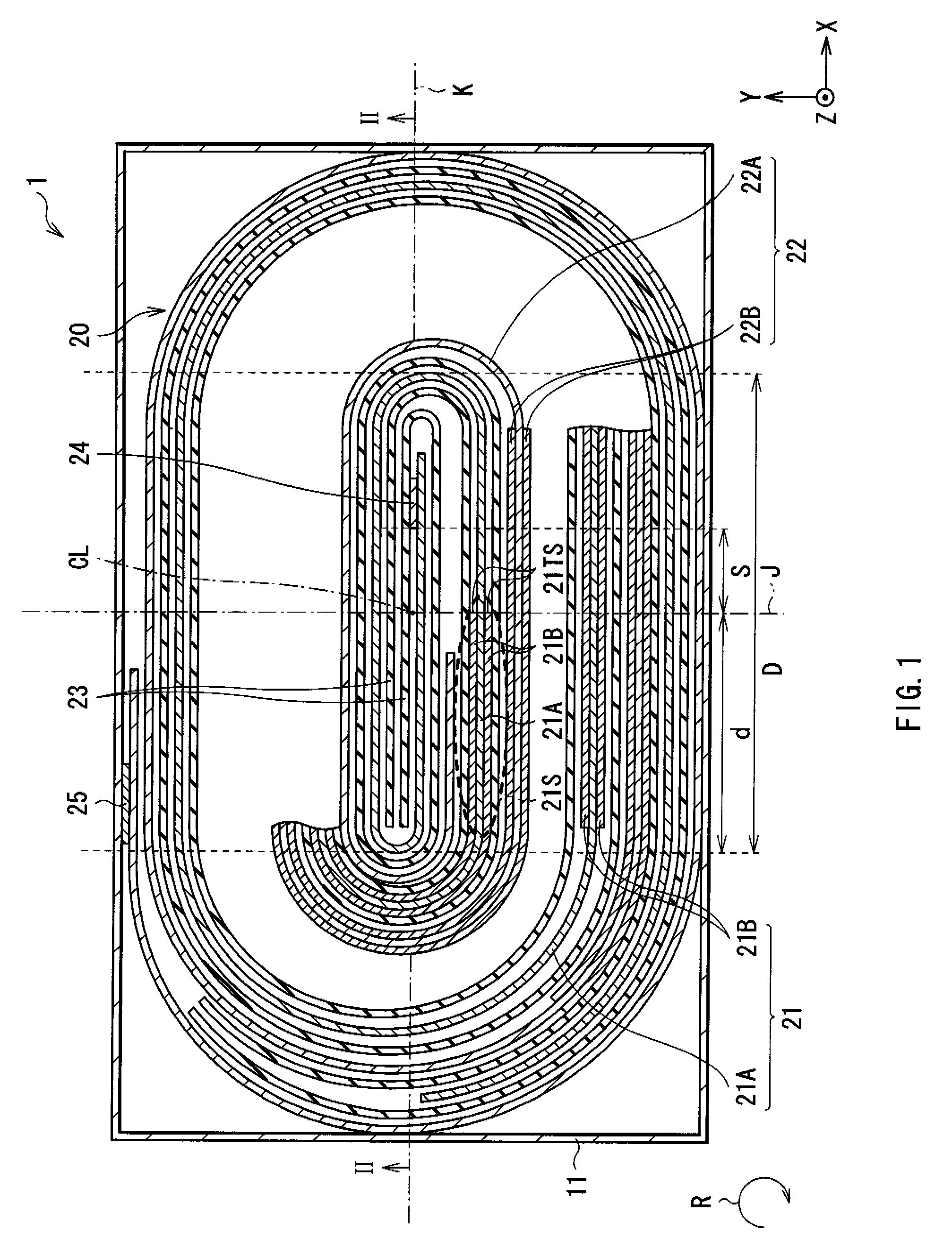
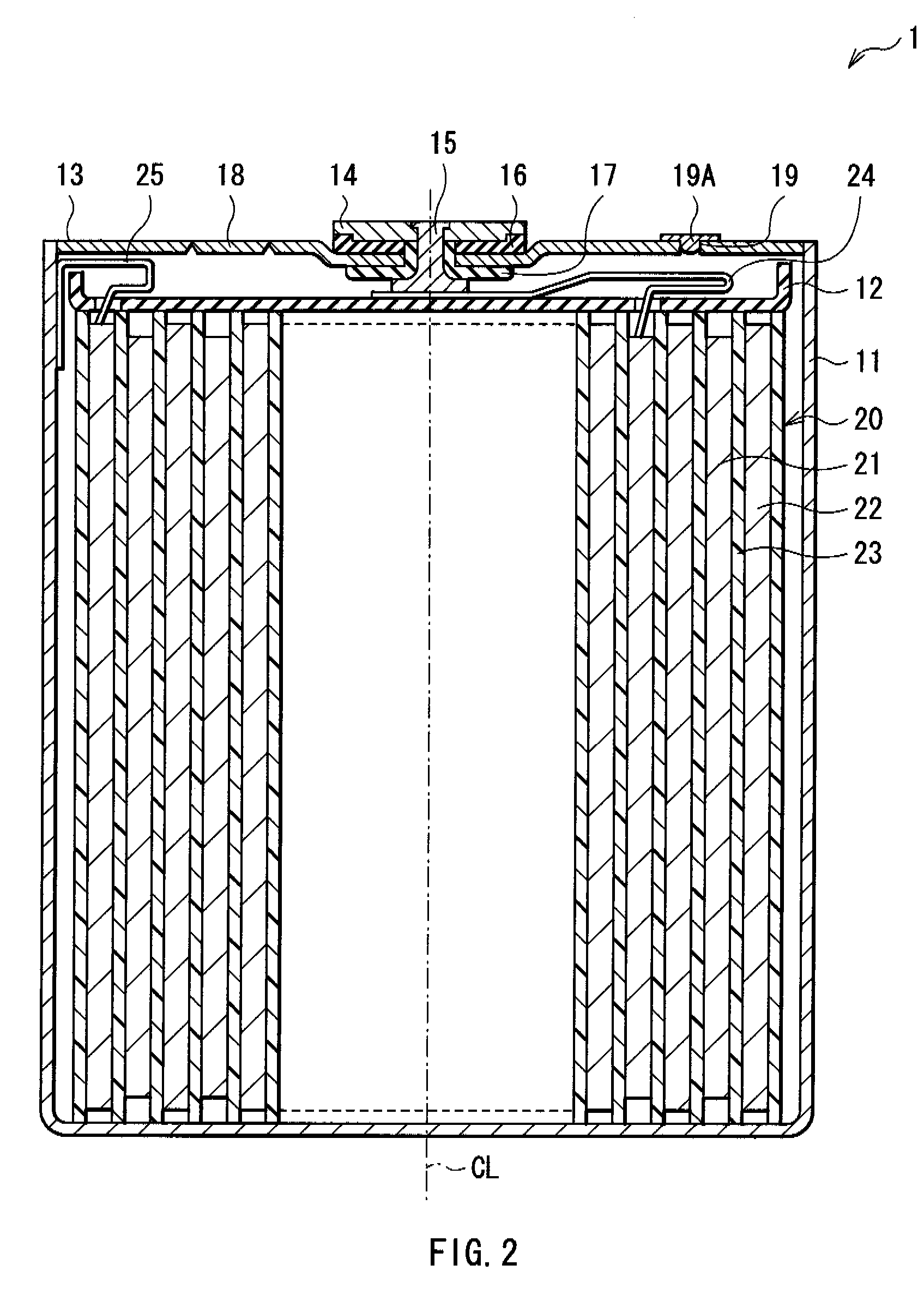
[0030]FIG. 1 and FIG. 2 show a cross sectional structure of a secondary battery 1 as a first embodiment of the invention. The secondary battery 1 is a so-called square secondary battery, and contains a planular spirally wound electrode body 20 inside a battery can 11 in the shape of an approximately hollow rectangular parallelepiped. The spirally wound electrode body 20 is a lamination film including a plurality of layers as described later, and is obtained by spirally winding the lamination film centering on a spirally winding axis CL. FIG. 1 shows a structure of a cross section perpendicular to the spirally winding axis CL. FIG. 2 shows a structure of a cross section cut taken along the long axis direction including the spirally winding axis CL. That is, FIG. 2 is a cross section in the arrow direction taken along line II-II shown in FIG. 1.

[0031]The battery can 11 is made of, for example, iron (Fe) plated by nickel (Ni). The battery can 11 also has a function as an anode terminal...

second embodiment

[0064]Subsequently, a description will be given of a secondary battery 2 as a second embodiment of the invention with reference to FIG. 5. FIG. 5 shows a cross sectional structure of the secondary battery 2, and corresponds to FIG. 1 showing the secondary battery 1 in the foregoing first embodiment. The secondary battery 2 has a structure similar to that of the secondary battery 1, except that a spirally wound electrode body 30 is included instead of the spirally wound electrode body 20. Therefore, a description will be given in such a manner that elements substantially identical with those of the secondary battery 1 are affixed with the same symbol, and the description thereof will be omitted as appropriate.

[0065]As shown in FIG. 5, the spirally wound electrode body 30 is formed to match with the shape of the battery can 11 in the cross section perpendicular to the spirally winding axis CL, and is planular shape having the long axis K (direction X) and the short axis J (direction Y...

third embodiment

[0072]Subsequently, a description will be given of a secondary battery 3 as a third embodiment of the invention with reference to FIG. 6. FIG. 6 shows a cross sectional structure of the secondary battery 3. The secondary battery 3 has a structure similar to that of the secondary battery 1 of the first embodiment, except that a spirally wound electrode body 40 is included instead of the spirally wound electrode body 20.

[0073]The spirally wound electrode body 40 has the both characteristics of the spirally wound electrode body 20 and the spirally wound electrode body 30. More specifically, in the spirally wound electrode body 40, the end face 21TS and the end face 21TE of the cathode active material layer 21B are located on one side of two regions divided by the long axis K. Further, the flat portion 21S and the flat portion 21E do not overlap with each other in the direction of the short axis J, and extend respectively from the end face 21TS and the end face 21TE to depart from each ...


PUM

PropertyMeasurementUnit
discharge voltageaaaaaaaaaa
thickaaaaaaaaaa
thickaaaaaaaaaa

Abstract

A battery that can secure the sufficient capacity, reduces deviation of the pressure distribution inside a spirally wound electrode body, and shows the superior charge and discharge characteristics is provided. The battery includes: a spirally wound electrode body in which a cathode having a cathode active material layer on a strip-shaped cathode current collector and an anode having an anode active material layer on a strip-shaped anode current collector are layered with a separator in between, and spirally wound in a planular state; and a lead jointed to the cathode current collector or the anode current collector in a center portion of the spirally wound electrode body. An inner circumferential end of the cathode active material layer is provided in a region where the inner circumferential end does not overlap with the lead in a short axis direction of the spirally wound electrode body.

Description

CROSS REFERENCES TO RELATED APPLICATIONS[0001]The present invention contains subject matter related to Japanese Patent Application JP 2006-138166 filed in the Japanese Patent Office on May 17, 2006, the entire contents of which being incorporated herein by reference.BACKGROUND OF THE INVENTION[0002]1. Field of the Invention[0003]The present invention relates to a secondary battery that includes a spirally wound electrode body in which a cathode and an anode are layered with an electrolyte in between and spirally wound.[0004]2. Description of the Related Art[0005]In recent years, many portable electronic devices such as a combination camera (Videotape Recorder), a mobile phone, and a notebook personal computer have been introduced, and downsizing and weight saving of such devices have been made. Research and development for improving the energy density of the battery used as a portable power source for such electronic devices, in particular the secondary battery as a key device has b...

Claims


Application Information

Patent Timeline
Patent Type & Authority Patents(United States)
IPC IPC(8): H01M6/12H01M2/02H01M2/26H01M4/13H01M4/134H01M4/136H01M4/38H01M4/58H01M10/05H01M10/052H01M10/0587
CPCH01M4/38H01M10/0525H01M10/0587Y02E60/122H01M4/386H01M4/387Y02E60/10Y02P70/50H01M4/364H01M4/583H01M4/134H01M10/052H01M10/0431H01M50/538H01M50/103
Inventor TAKAGI, KUMIKOHASHIMOTO, FUMIKOYAMAGUCHI, AKIRAFUKUSHIMA, YUZURUINOUE, HIROSHIMINATO, YASUFUMI
Owner MURATA MFG CO LTD
Why Eureka
Try Eureka