Lighting system

a technology of lighting system and light source, which is applied in the direction of lighting and heating apparatus, semiconductor devices for light sources, furniture parts, etc., can solve the problems of increasing cost and time-to-market, requiring power,

Inactive Publication Date: 2016-03-08
SIGNIFY HLDG BV +1
View PDF23 Cites 13 Cited by
  • Summary
  • Abstract
  • Description
  • Claims
  • Application Information

AI Technical Summary

Benefits of technology

[0005]In a first example of the present invention, a lighting system is provided. The lighting system comprises a plurality of discrete light emitting diode modules and a translucent portion containing the plurality of discrete light emitting diode modules. Each light emitting diode module comprises a light emitting diode and at least a first module electrode and a second module electrode. The first module electrode is in electrical connection with the cathode of the light emitting diode and the second module electrode is in electrical connection with the anode of the light emitting diode. At least a portion of the plurality of light emitting diode modules form a string of modules, with at least one module electrode of each of the light emitting diode modules in the string being in direct physical contact with a light emitting diode module electrode of a neighboring light emitting diode module in the string such that, when a voltage is applied across the string, current flows in each light emitting diode module in the string thereby activating the light emitting diode of each light emitting diode module in the string. The lighting system can take many different shapes or forms without requiring the provision of a bespoke, or indeed any, wiring system connecting the light emitting diode modules. Consequently, designers have more freedom to make lighting systems of many different shapes without also needing to consider the design of specific wiring patterns to suit each different system.
[0006]The plurality of discrete light emitting diode modules may be irregularly distributed within the translucent portion. As such, the LED modules need not be specifically arranged within the system. This reduces both the time and cost associated with creating a lighting system.

Problems solved by technology

An important limitation for embedding LEDs into a material is that they require power.
This is a flexible solution, but it requires a redesign of the wiring structure for each new object shape, which increases the cost and the time-to-market.

Method used


Image

  • Lighting system
  • Lighting system
  • Lighting system

Examples


Embodiment Construction

[0029]In the description and drawings, like reference numerals refer to like surface electrodes throughout.

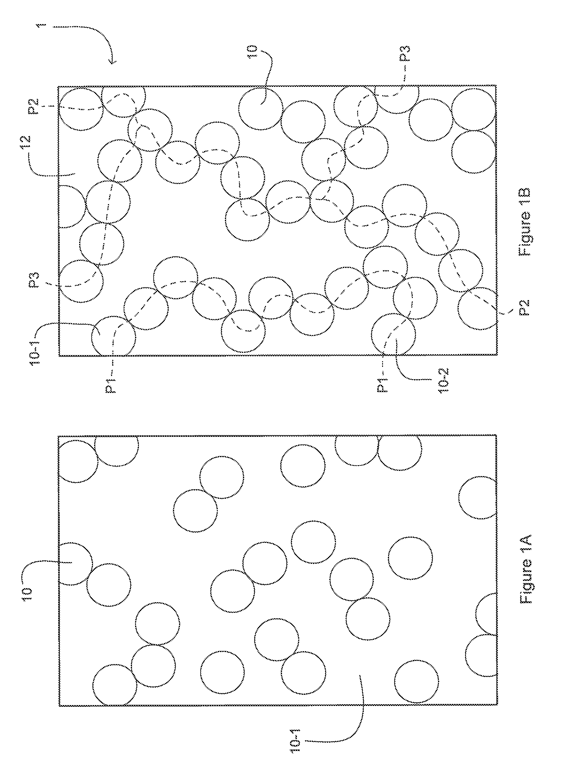
[0030]FIGS. 1A and 1B illustrate how the invention makes use of the physical effect known as “percolation”. Specifically, the invention makes use of percolation of electric energy along randomly-formed conductive paths in an insulating filler material.

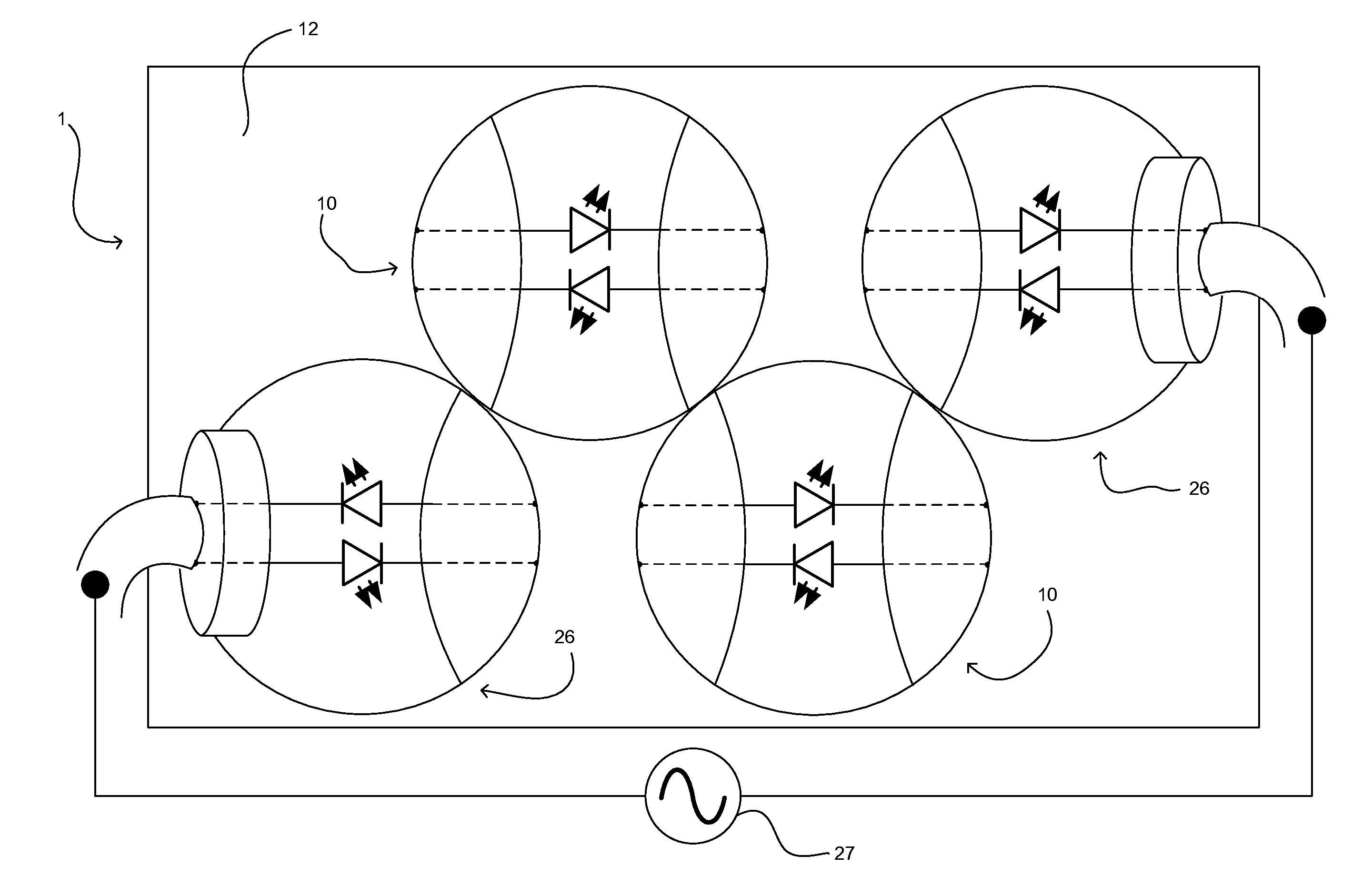
[0031]FIG. 1A shows a composite material including a relatively low number of discrete light emitting diode (LED) modules 10 distributed within an insulating filler (or bulk) material 12.

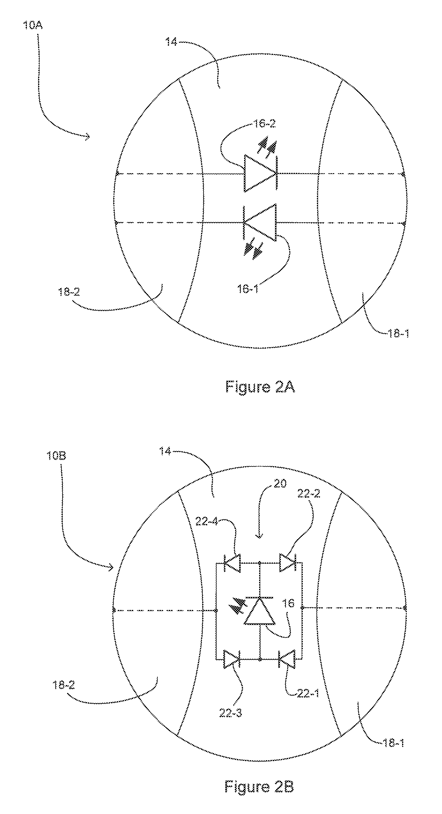
[0032]Although not visible in FIG. 1A, each of the LED modules 10 comprises at least one LED and first and second module electrodes. The module electrodes are comprised of an electrically conductive material. Each of the first and second module electrodes is in electrical connection with at least one of the anode and cathode of the LED. Each LED module 10 is operable to receive electrical current from, and to pass electric current to, a neighborin...


PUM


Abstract

A lighting system comprises a plurality of discrete light emitting diode modules and a translucent portion containing the plurality of discrete light emitting diode modules. Each light emitting diode module comprises a light emitting diode and at least a first module electrode and a second module electrode. The first module electrode is in electrical connection with the cathode of the light emitting diode and the second module electrode is in electrical connection with the anode of the light emitting diode. At least a portion of the plurality of light emitting diode modules form a string of modules, with at least one module electrode of each of the light emitting diode modules in the string being in direct physical contact with a module electrode of a neighboring light emitting diode module in the string such that, when a voltage is applied across the string, current flows in each light emitting diode module in the string thereby activating the light emitting diode of each light emitting diode module in the string.

Description

CROSS-REFERENCE TO PRIOR APPLICATIONS[0001]This application is the U.S. National Phase application under 35 U.S.C. §371 of International Application No. PCT / IB2012 / 056832, filed on Nov. 29, 2012, which claims the benefit of [e.g., U.S. Provisional Patent Application No. or European Patent Application No.] 61 / 566,754, filed on Dec. 5, 2011. These applications are hereby incorporated by reference herein.FIELD OF THE INVENTION[0002]The invention relates to a lighting system. Specifically, the invention relates to a lighting system comprising light emitting diodes.BACKGROUND OF THE INVENTION[0003]The availability of light emitting diodes (LEDs) that are suitable for general illumination purposes allows for the use of LED light sources in many different scenarios. Designers all over the world are currently investigating new designs that are made possible by the small form factor and low-voltage driving of LEDs. These features enable easy integration of LED light sources in the interior (...

Claims


Application Information

Patent Timeline
Patent Type & Authority Patents(United States)
IPC IPC(8): F21V23/02F21V23/06F21S2/00F21V31/00F21S4/00F21V33/00F21S10/02F21W121/00F21W131/301
CPCF21V23/02F21V23/06F21V31/005F21S4/10F21S2/005F21S4/00F21S10/02F21V33/006F21V33/0012F21W2121/00F21W2131/301F21Y2101/02F21Y2115/10
Inventor VISSENBERG, MICHEL CORNELIS JOSEPHUS MARIEJACOBS, JOHANNES ANDREAS HENRICUS MARIAVAN GORKOM, RAMON PASCALVERHOEVEN, MARK JOHANNES ANTONIUSDUIJMELINK, ANDREAS ALOYSIUS HENRICUSCOOIJMANS, HUIB
Owner SIGNIFY HLDG BV
Why Eureka
Try Eureka