Optical imaging system

a technology of optical imaging and optical lens, applied in the field of optical imaging system, can solve the problems of reducing imaging quality and unsatisfactory imaging quality in wide angle observation, and achieve the effect of short structural length and high imaging quality

Active Publication Date: 2016-03-08
CARL ZEISS MEDITEC AG
View PDF17 Cites 0 Cited by
  • Summary
  • Abstract
  • Description
  • Claims
  • Application Information

AI Technical Summary

Benefits of technology

[0007]It is an object of the invention to provide an optical imaging system, in which a very high imaging quality is achieved when using a reduction optical unit ahead of a main objective. Furthermore, it is an object to provide an imaging system with a short structural length.
[0019]The aforementioned condition can be satisfied well by using materials with high refractive indices, that is greater than 1.6, for the first and second lenses of the reduction optical unit. As a result, a well corrected image with a very good contrast and a low chromatic angle deviation advantageously emerges.
[0021]The distance of the object plane to be observed from the main objective may vary. As a result, it may be necessary to adapt the focus of the optical observation apparatus to the modified object plane. In order to allow the focus setting of the microscope to stay unchanged, it is advantageous if the reduction optical unit offers the option of focusing. This focusing option can be achieved relatively easily by virtue of the first lens of the reduction optical unit being disposed in a stationary manner and the second lens being able to perform a relative movement along the optical axis. With the optical imaging system of the invention, a good correction of the chromatic angle deviation is ensured over the whole focusing range.
[0023]The same advantages as described in the preceding embodiment can be achieved if the second lens of the reduction optical unit is disposed in a stationary manner and the first lens of the reduction optical unit is disposed displaceably in the direction of the optical axis.
[0025]In order to enable the user of a microscope to work alternatively with or without the reduction optical unit, it is advantageous if the reduction optical unit can be simply introduced into the beam path or removed from the beam path. As a result, the user can quickly and easily switch back-and-forth between two focus planes without having to change the focus setting of the microscope. Advantageously, the reduction optical unit can be pivoted into and out of the beam path ahead of the main objective very easily and quickly by means of a pivoting device.
[0029]The lenses of the reduction optical unit are usually embodied in a rotationally symmetric manner with respect to the optical axis. As a result of the optical axis of the main objective and the optical axis of the reduction optical unit being identical, the optical chromatic correction for all observation beam paths extending at a distance B from the optical axis with respect to the two main planes H and H′ is equally good. For a stereo microscope, an advantage emerging from this is that both observation beam paths are corrected equally well chromatically by a single reduction optical unit. This advantage also applies to each further observation beam path guided at a distance B from the optical axis in respect of the two main planes H and H′.

Problems solved by technology

A disadvantage of this microscope is that the imaging quality in the wide angle observation is not ideal.
The wide angle optical unit can be adapted to the microscope by means of a further reduction optical unit which can be introduced into the beam path; however, this is linked to the disadvantage of a reduced imaging quality.

Method used


Image

  • Optical imaging system
  • Optical imaging system
  • Optical imaging system

Examples


Embodiment Construction

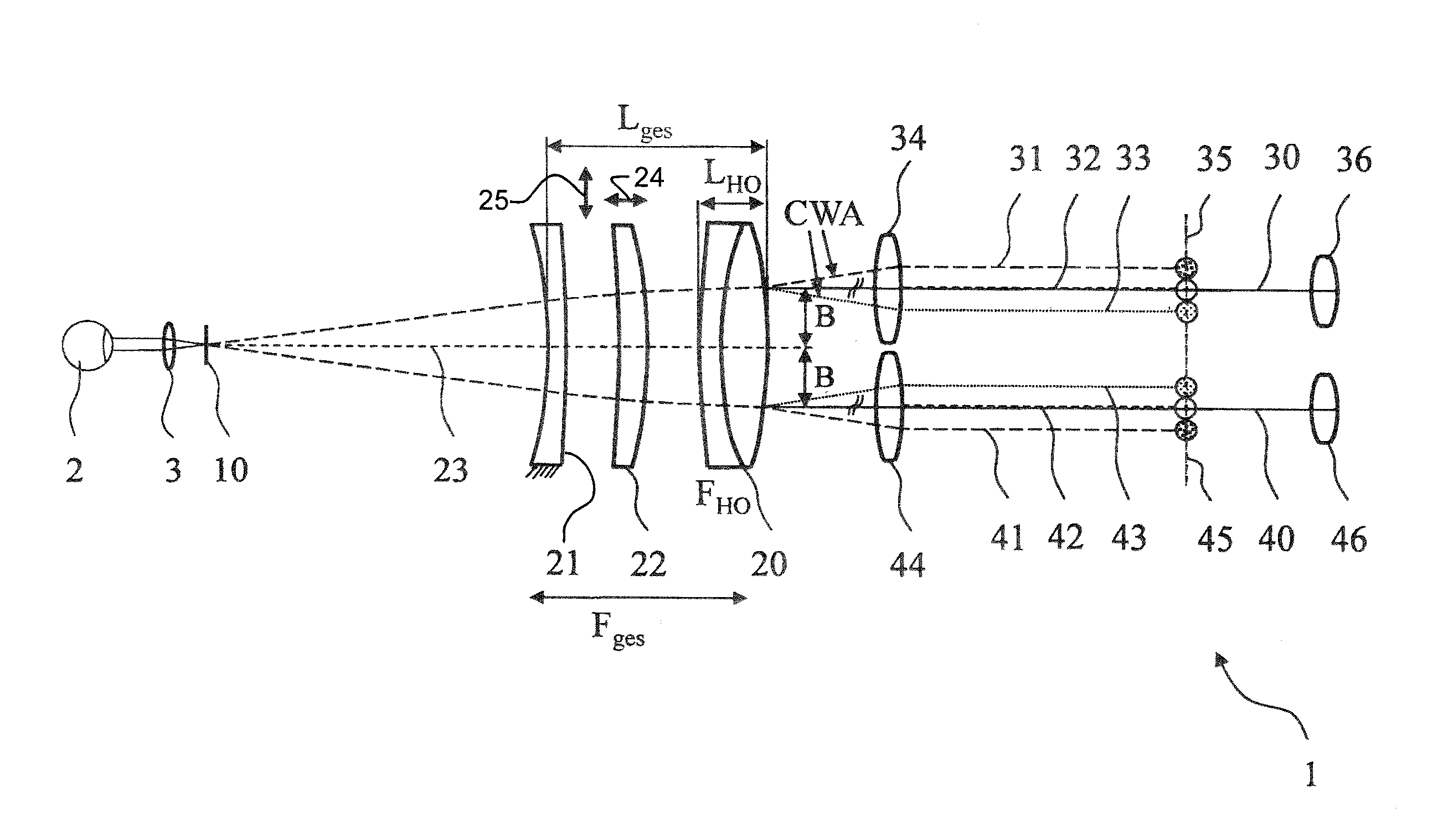
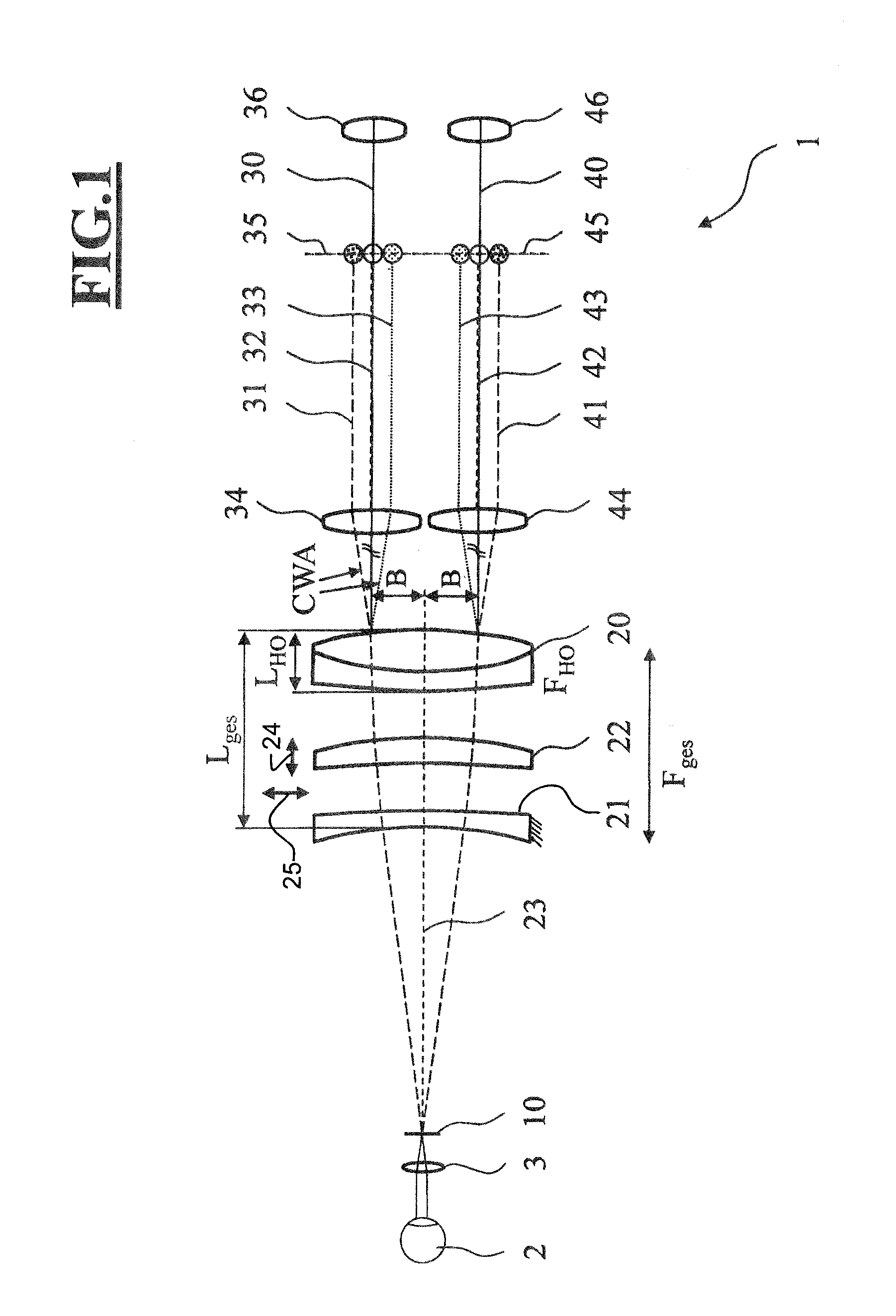
[0034]FIG. 1 depicts an exemplary embodiment of an optical imaging system 1 according to the invention, including a reduction optical unit mounted ahead of a main objective 20.

[0035]The exemplary embodiment shows an optical imaging system 1 for observing an eye 2. The optical imaging system 1 is configured as a stereoscopic observation system with a right-hand observation beam path 30 and a left-hand observation beam path 40 and includes a main objective 20 with an optical axis 23, a right-hand tube lens 34, a left-hand tube lens 44 and a right-hand eyepiece 36 and a left-hand eyepiece 46. It may comprise further optical elements not depicted here.

[0036]A further optical element in the form of an ophthalmic lens 3 and a reduction optical unit in the form of two lenses have been introduced into the beam path between the main objective 20 and the eye 2. A first lens of the reduction optical unit disposed directly ahead of the main objective 20 is embodied as a positive lens 22 and has...


PUM


Abstract

An optical imaging system generates an image of an object plane and includes a lens system which, in turn, includes a main objective and a reduction optical unit ahead of the main objective. The lens system is aligned along an optical axis and the reduction optical unit includes a first lens with a positive refractive power and a second lens with a negative refractive power. An object-side first main plane and an image-side second main plane are defined by the lens system. The optical imaging system defines an observation beam path which is guided through the lens system so that, in the first main plane and in the second main plane, the observation beam path is at a distance (B) from the optical axis. The first lens is of a first material having a first Abbe number and the second lens is of a second material having a second Abbe number, wherein the first Abbe number is greater than the second Abbe number.

Description

CROSS REFERENCE TO RELATED APPLICATION[0001]This application claims priority of German patent application no. 10 2013 219 379.3, filed Sep. 26, 2013, the entire content of which is incorporated herein by reference.FIELD OF THE INVENTION[0002]The invention relates to an optical imaging system, in particular a microscope, for generating an image of an object plane, including a lens system which includes a main objective and a reduction optical unit between the main objective and the object plane and which is aligned along an optical axis. The reduction optical unit includes a first lens with a positive refractive power and a second lens with a negative refractive power. An object-side first main plane and an image-side second main plane are defined by the lens system. The optical imaging system defines an observation beam path which is guided through the lens system in such a way that, in the first main plane and in the second main plane, the observation beam path in each case has a d...

Claims


Application Information

Patent Timeline
Patent Type & Authority Patents(United States)
IPC IPC(8): G02B21/00G02B21/02A61B3/12G02B21/22
CPCG02B21/0012A61B3/12G02B21/02G02B21/22G02B21/20
Inventor MERZ, FRANZHOEGELE, ARTUR
Owner CARL ZEISS MEDITEC AG
Why Eureka
Try Eureka