
Antenna circuit and a method of optimisation thereof

a technology of antenna circuit and antenna circuit, applied in the field of tunable antennae, can solve problems such as signal jamming, and achieve the effects of suppressing signal jamming, good transmission and reception signal isolation, and small magnitud

Active Publication Date: 2016-03-15
HONG KONG APPLIED SCI & TECH RES INST
View PDF7 Cites 4 Cited by
  • Summary
  • Abstract
  • Description
  • Claims
  • Application Information

AI Technical Summary

Benefits of technology

Enables the use of mobile devices as RFID detectors with improved signal isolation and reception, allowing for the detection of RFID tagged objects without the need for additional manpower, while maintaining a compact form factor.

Problems solved by technology

Signal jamming is caused when the signal leakage from the input port into the isolation port is big enough to mask any signal reflected from an RFID tag.

Method used


Image

  • Antenna circuit and a method of optimisation thereof
  • Antenna circuit and a method of optimisation thereof
  • Antenna circuit and a method of optimisation thereof

Examples


Embodiment Construction

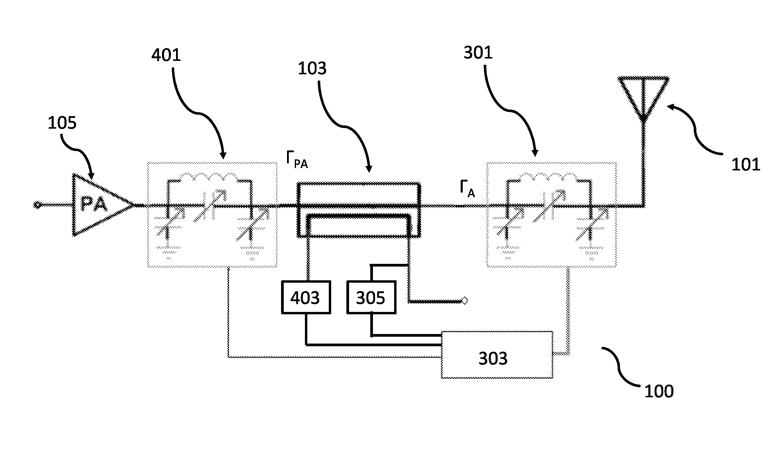
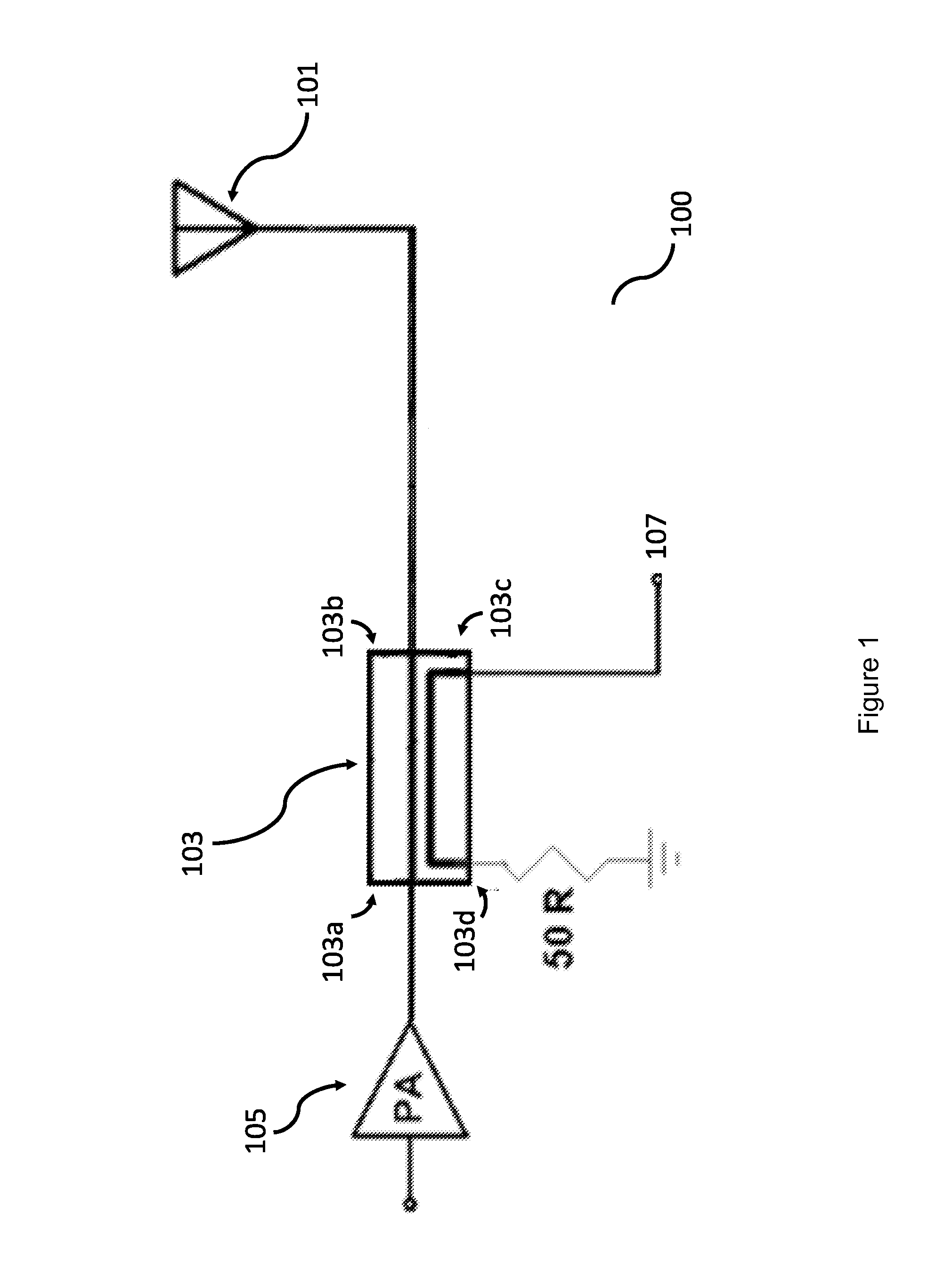
[0080]FIG. 1 shows an RFID antenna circuit 100 comprising an antenna 101 for sending out probing signals into the surroundings. Any RFID tag in the vicinity will reflect the signal back to the antenna 101 for identification. The antenna 101 is connected to a directional coupler 103 to isolate probing signals broadcasted from the antenna from reflected signals received by the antenna.

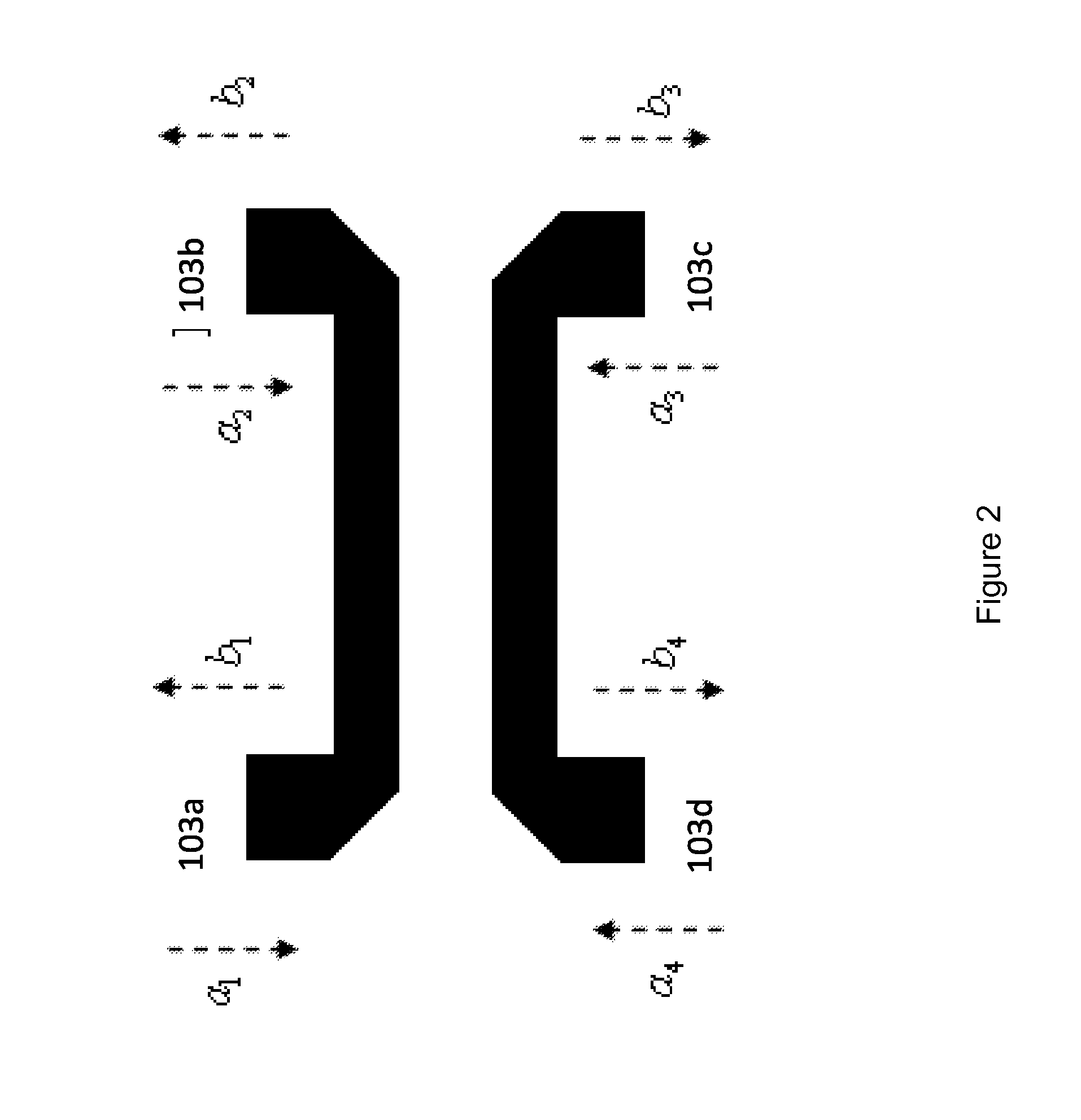
[0081]FIG. 2 show that a typical directional coupler 103 having port 1103a, port 2103b, port 3103c, and port 4103d.

[0082]Port 1 is known as the input port and is connected to a power source. Typically, signal is fed into port 1 from a power amplifier 105.

[0083]Port 2 is known as the output port and is connected to the antenna 101. Signal from the directional coupler 103 is transmitted from port 2 to the antenna 101 for broadcast.

[0084]Port 3 is known as the isolation port. Basically, the directional coupler 103 allows signals to travel bi-directionally. In one direction, a signal can travel directly fro...


PUM


Abstract

An antenna circuit is having an impedance circuit which can cancel signal leakage from the input port into the isolation port of a directional coupler. The antenna circuit further comprises a second impedance circuit for optimizing power transfer from the input port to the output port of the directional coupler. Furthermore, the antenna is tunable in order to maximize the reception strength of the antenna. The antenna circuit provides at once the possibility of tuning the antenna strength, optimizing the power transmission and reducing signal jamming by cancelling signal leakage. The antenna finds use as an effective and miniature RFID antenna.

Description

FIELD OF INVENTION[0001]This invention relates to tunable antennae and, in particular, tunable RFID (radio frequency identity) antenna circuits for use in handheld, portable devices such as mobile telephones.BACKGROUND OF INVENTION[0002]Although RFID technology is used almost everywhere, its purchase, implementation and access of use are unfortunately limited to buyers of entire, proprietary systems and their permitted users. Organisations which would implement an RFID system are those which have a large number of physical objects to monitor, such as warehouses, libraries, departmental stores and so on. An RFID system implemented in these premises cannot be used by any casual member of the public to locate RFID tagged objects because the member of the public will need a suitable RFID detector and will also need to be given a database to identify objects which are detected by RFID. This causes great inconvenience at a huge cost to the management of these premises because manpower wou...

Claims


Application Information

Patent Timeline
Patent Type & Authority Patents(United States)
IPC IPC(8): G06K7/10H01Q1/22H03H7/46H01P5/18H01Q7/00H03H7/40H04B1/525
CPCH01Q7/005H01Q1/2216H03H7/40
Inventor WAN, TAK KILIU, YANHE, SONGYANG, DANMAK, CHI KEUNG ANGUS
Owner HONG KONG APPLIED SCI & TECH RES INST
Learn More