Electric machine—over-moulding construction

a technology of electric machines and construction, applied in the direction of windings, stator/rotor bodies, magnetic circuit shapes/forms/construction, etc., can solve the problems of significant heat generation and inadequate cooling, and achieve the effect of enhancing the efficiency of the machin

Active Publication Date: 2016-03-15
YASA LIMITED
View PDF49 Cites 27 Cited by
  • Summary
  • Abstract
  • Description
  • Claims
  • Application Information

AI Technical Summary

Benefits of technology

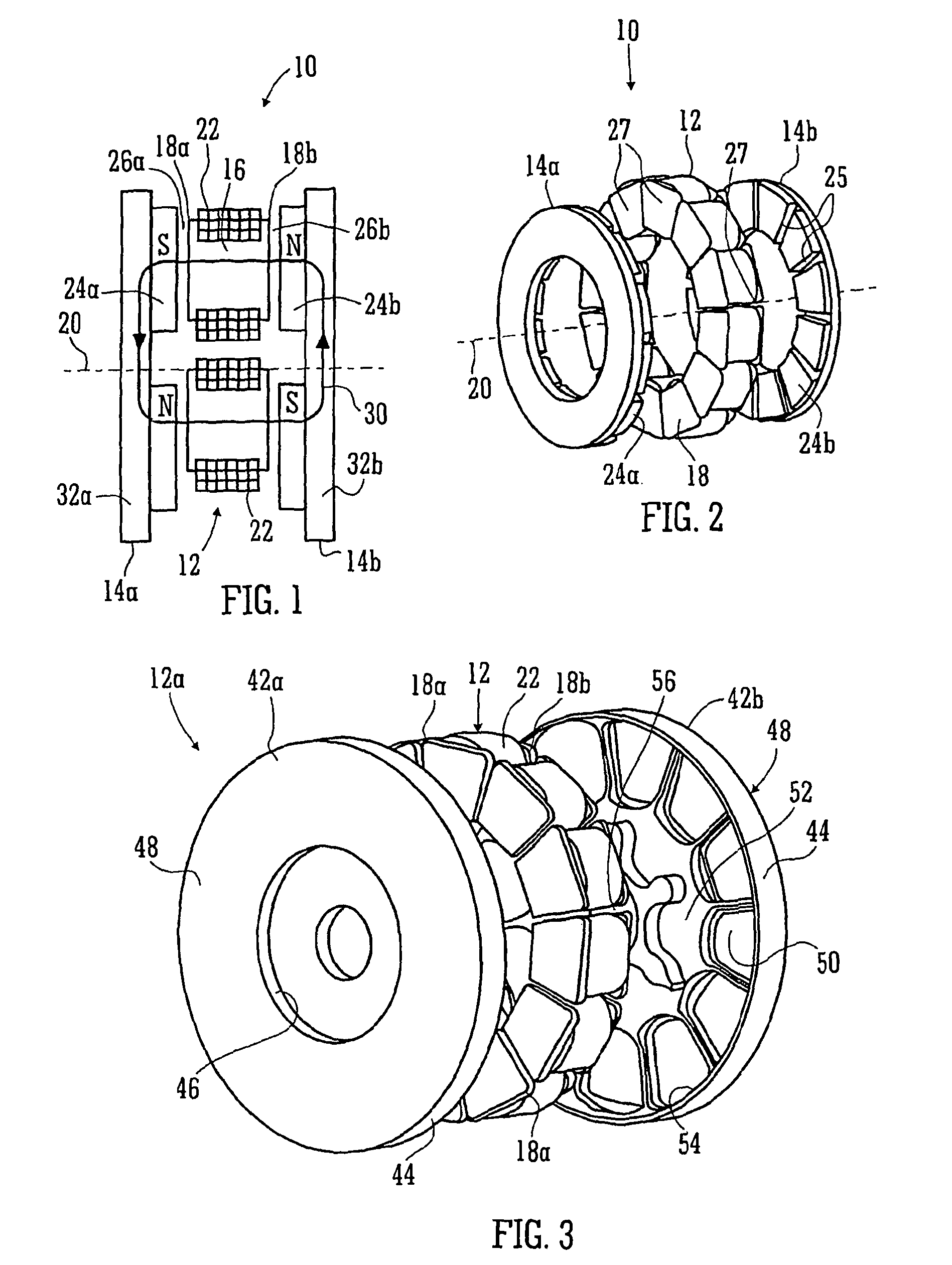
[0046]Each radial wall may extend through the air gap and is thinned where the shoes of each bar are retained to minimize the gap between the bars and the magnets on the rotor.
[0047]By overmoulding the stator shoes in the clamshell, the position of them in the machine can be fixed, the mould serving as a jig to hold the stator shoes in correct position with respect to one another and the clamshell serving to maintain that juxtaposition during assembly. In addition, the stator shoes being moulded in the clamshells, which are ultimately connected together to form the stator, provides a rigid construction of the stator, enabling the air gap between the stator shoes and rotor magnets to be minimised, whereby the efficiency of the machine is enhanced.

Problems solved by technology

One difficulty with electric machines generally is to provide adequate cooling.
This is a particular problem with a Y machine having a high torque density that significant heat is generated in the coils at high torques and is often a limiting factor in the torques that can be employed, at least for extended periods of time.

Method used


Image

  • Electric machine—over-moulding construction
  • Electric machine—over-moulding construction
  • Electric machine—over-moulding construction

Examples


Embodiment Construction

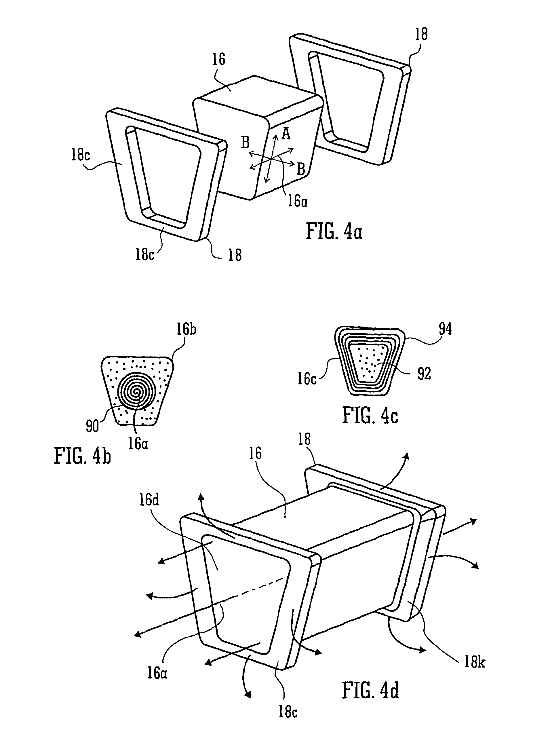
[0060]A yokeless and segmented armature machine 10 is illustrated schematically in FIG. 1. The machine 10 comprises a stator 12 and two rotors 14a,b. The stator 12 is a collection of separate stator bars 16 spaced circumferentially about a rotation axis 20 of the rotors 14a,b. Each bar 16 has its own axis 16a which is disposed parallel to the rotation axis 20. However, that is not absolutely essential. In an axial flux machine, the axis 16a is indeed parallel the rotation axis 20. However, it can be disposed at any angle thereto, even radially with respect to the rotation axis 20. The following discussion is in respect of an axial flux machine, but this should not be understood to be limiting in any sense and, where the context permits, the invention equally applies to other inclinations of the stator bars 16.

[0061]Each end of each stator bar is provided with a shoe 18a,b which serves a physical purpose of confining a coil stack 22, which stack 22 is preferably of square section ins...


PUM

PropertyMeasurementUnit
temperatureaaaaaaaaaa
stress concentrationsaaaaaaaaaa

Abstract

An electric machine (10) comprises a rotor (14a, b) having permanent magnets (24a, b) and a stator (12) having coils (22) wound on stator bars (16) for interaction with the magnets across an air gap (26a, b) defined between them. The bars (16) and coils (22) are enclosed by an annular stator housing (42a, b) that extends between the air gap. A chamber (52, 54, 56) is defined that incorporates cooling medium to cool the coils. The stator housing comprises two mating clamshells (42a, b) that mount the stator bars and coils in the machine. Each clamshell is molded from reinforced plastics and interconnected (optionally through one or more intermediate components). At least one clamshell has over-molded therein stator bar shoes that form part of said radial wall, and optionally one or more of the following components: cylindrical boss supports extending along the cylindrical outer wall part; connection studs that communicate electrically the chamber externally; stator coils; coolant inlet and outlet ports; and an outer race of a rotor bearing.

Description

[0001]This invention relates to a permanent magnet electric machine comprising a stator and a rotor journalled for rotation in the stator, and a method of constructing such a machine. The stator is provided with coils wound on stator bars and the rotor is provided with permanent magnets to cooperate with the coils across an air gap between the rotor and stator. The machine may be either a motor or a generator and is in many embodiments an axial flux machine. In particular, the present invention relates to a yokeless and segmented armature machine, hereinafter termed a “Y machine”, and a method of constructing such a machine.BACKGROUND[0002]Woolmer and McCulloch [1] describe the topology of a Y machine, discussing its advantages of reduced iron in the stator enabling an improvement in torque density. It comprises a series of coils wound around bars spaced circumferentially around the stator, ideally axially disposed, (ie parallel the rotation axis of the rotor). The rotor has two sta...

Claims


Application Information

Patent Timeline
Patent Type & Authority Patents(United States)
IPC IPC(8): H02K9/28H02K15/02H02K1/14H02K21/24H02K5/20H02K3/52H02K5/22H02K9/19
CPCH02K9/28H02K1/14H02K3/521H02K5/20H02K15/02H02K21/24H02K5/225H02K9/19Y10T29/49009H02K5/203H02K1/182H02K15/022H02K3/24H02K9/197H02K15/12H02K15/0093
Inventor WOOLMER, TIMGARDNER, CHRISBARKER, JON
Owner YASA LIMITED
Why Eureka
Try Eureka