Linear solid-state lighting with a wide range of input voltage and frequency free of fire and shock hazards

a solid-state lighting and input voltage technology, applied in lighting and heating equipment, process and machine control, instruments, etc., can solve the problems of high total cost of ownership, inability to accurately detect ballasts and replace incompatible parts, and complex maintenance, so as to eliminate the risk of electric shock and accurate output led current

Active Publication Date: 2016-03-15
ALEDDRA INC
View PDF4 Cites 53 Cited by
  • Summary
  • Abstract
  • Description
  • Claims
  • Application Information

AI Technical Summary

Benefits of technology

[0012]A universal linear LED tube (LLT) lamp comprising a housing having two ends; an LED printed circuit board (PCB) with a plurality of LEDs connected as LED arrays; a lens; a bridge rectifier having two inputs connecting to one of two pins of a bi-pin at each end of the lamp; an all-in-one LED driving circuit; and two input modules each comprising a shock protection switch, is used to replace a fluorescent tube in a retrofit or newly-made linear tube lamp fixture that could have an existing electronic ballast or simply an AC mains-ready configuration. When such a universal LLT lamp is installed in the fixture, the all-in-one LED driving circuit can detect how high an input voltage and frequency and make proper and necessary management so that the universal LLT lamp can operate with the existing electronic ballast or simply with the AC mains without operational uncertainty. When such a configuration in the all-in-one LED driving circuit is used with shock protection switches on both ends of the universal LLT lamp, the shock protection switches can effectively block an electric current flowing through the all-in-one LED driving circuit to an exposed bi-pin not yet installed in the fixture sockets, no matter whether the current is from the AC mains or a ballast. Experimental results show that ballast output voltage and current can burn a person's skin, creating an electric shock hazard as the AC mains. With shock protection switches on both ends of the universal LLT lamp, no line voltage or leakage current from the ballast will possibly appear at the exposed bi-pin during initial installation or re-lamping, thus completely eliminating risks of electric shocks.
[0013]The all-in-one LED driving circuit comprises an input filter, a power factor correction (PFC) and control device, a Buck converter in communicating with the PFC and control device, an output capacitor in parallel with a resistor connected to the Buck converter to build up an output voltage and to power the LED arrays, and a voltage feedback module extracting partial energy from the output voltage to sustain the PFC and control device. The Buck converter comprises a switch controlled by the PFC and control device, a current sensing resistor, a diode, and an inductor with its current charging and discharging controlled by the switch. The PFC and control device detects zero current in the inductor within an AC cycle of an input voltage generating a zero current detection signal and controls the switch on and off with a constant on-time and a varied off-time controlled by the zero current detection signal. By adapting switching frequencies for a high frequency associated with a ballast and a low frequency associated with the AC mains, the all-in-one LED driving circuit can provide an accurate output LED current required to operate the LED arrays no matter what input voltage is high ballast output voltage or regular 110 or 277 VAC from the AC mains. Not like prior art schemes that use an AC impedance control working only for ballast, the all-in-one LED driving circuit adopts a switching mode power supply with regulated output power and current rather than through the AC impedance control. The same switching mode power supply used in the all-in-one LED driving circuit to work with the ballast can also apply to a LLT lamp in operating with the AC mains.
[0014]Because double shock protection switches are used in both ends of the lamp, consumers can safely install such a universal LLT lamp in an existing lamp fixture used to operate a conventional fluorescent tube without operational uncertainty and electric shock hazards, no matter how the fixture is wired, double-ended AC mains or electronic ballast. The universal LLT lamp can immediately be used with an existing electronic ballast in a fixture without rewiring. When the ballast dies, consumers may choose to replace it with a new one at cost or just to bypass it and to electrically connect the fixture as an AC mains-operable one. In the latter case, the consumers can just install the universal LLT lamp back into the fixture without worrying about possible electric shock hazard that may occur when they accidentally touch an exposed bi-pin on the other end of the lamp, or possible fire hazard due to a large dc capacitor used or an unregulated current flow in a conventional LED driving circuit.

Problems solved by technology

But the fact is that total cost of ownership for this approach is high regardless of very low initial cost.
If the existing ballast is not compatible with the ballast-compatible LLT lamp, the consumer will have to replace the ballast.
Some facilities built long time ago incorporate different types of fixtures, which requires extensive labor for both identifying ballasts and replacing incompatible ones.
Maintenance will be complicated, sometimes for lamps and sometimes for ballasts.
The labor costs and long-term maintenance costs will be unacceptable to end users.
In the long run, ballast-compatible LLT lamps are more expensive and less efficient than self-sustaining AC mains-operable LLT lamps.
In some prior art schemes, a switching mode power supply (SMPS) type LED driver is proposed to use with a ballast, but has not been completely accepted due to occasional fires that arise inside the ballast.
The cause of these fires has been identified to be a large dc input capacitor in the SMPS type LED driver, which may destroy a capacitor in the ballast due to excessive initial resonant voltage.
Such a Buck converter is controlled by a control logic, which has several drawbacks that limit its use in ballast applications.
First, the control logic has a low operating voltage range which inherently limits the wide range of input voltages that can be used.
Third, the Buck converter operates in a continuous conduction mode, in which an input current fails to follow the input voltage, leading to a low power factor with AC mains and turn-on or other operational failures with the ballast.
When the input voltage drops to the minimum operating voltage level, the control logic fails to operate and sends no signals to the switch, and the Buck converter stops to function until the input voltage level recovers, rendering flicker.
In the worst case, an LED tube lamp that is designed for a group of three or four lamps in a fixture powered by a ballast may be burned out due to over-rated current flowing into the LED arrays in the lamp if it is installed alone in the fixture.
For the output voltage control approach, it may work with an electronic ballast but cannot be used in AC mains.
In general, conventional LED drivers fail to work with a ballast and to properly operate an LED tube lamp at a regulated power, resulting in unstable lighting output.
However, the frequency sensing and control mechanism used in the LLT lamp needs additional sensing and control devices, of which reliability may be compromised.
Furthermore, when an AC voltage from a ballast is supplied to the LED driving circuit in the LLT lamp, the frequency sensing and control mechanism directs a DC current rectified from the AC voltage output of the ballast to an output capacitor without regulation, which may yield an undesirable output power.
In that case, once the LED arrays in the LLT lamp are not in place as a load to dissipate the energy stored in the output capacitor, the voltage across it may exceed its rating and burn it resulting in an internal fire in the LED driving circuit.
All the LLT lamps, no matter whether AC mains-operable or ballast compatible, have one construction issue related to product safety and needed to be resolved prior to wide field deployment.
This kind of LLT lamps always fails a safety test, which measures through lamp leakage current.
Because a high AC voltage applies to both opposite ends of the tube when connected to a power source, the measurement of current leakage from one end to the other consistently results in a substantial current flow, which may present a risk of shock during re-lamping.
In fact, when a high AC voltage from a ballast applies to LLT lamps, the same electric shock hazard exists.
Experimental results show a person's skin may be burned due to such an electric shock.
Experimental results show that ballast output voltage and current can burn a person's skin, creating an electric shock hazard as the AC mains.

Method used


Image

  • Linear solid-state lighting with a wide range of input voltage and frequency free of fire and shock hazards
  • Linear solid-state lighting with a wide range of input voltage and frequency free of fire and shock hazards
  • Linear solid-state lighting with a wide range of input voltage and frequency free of fire and shock hazards

Examples


Embodiment Construction

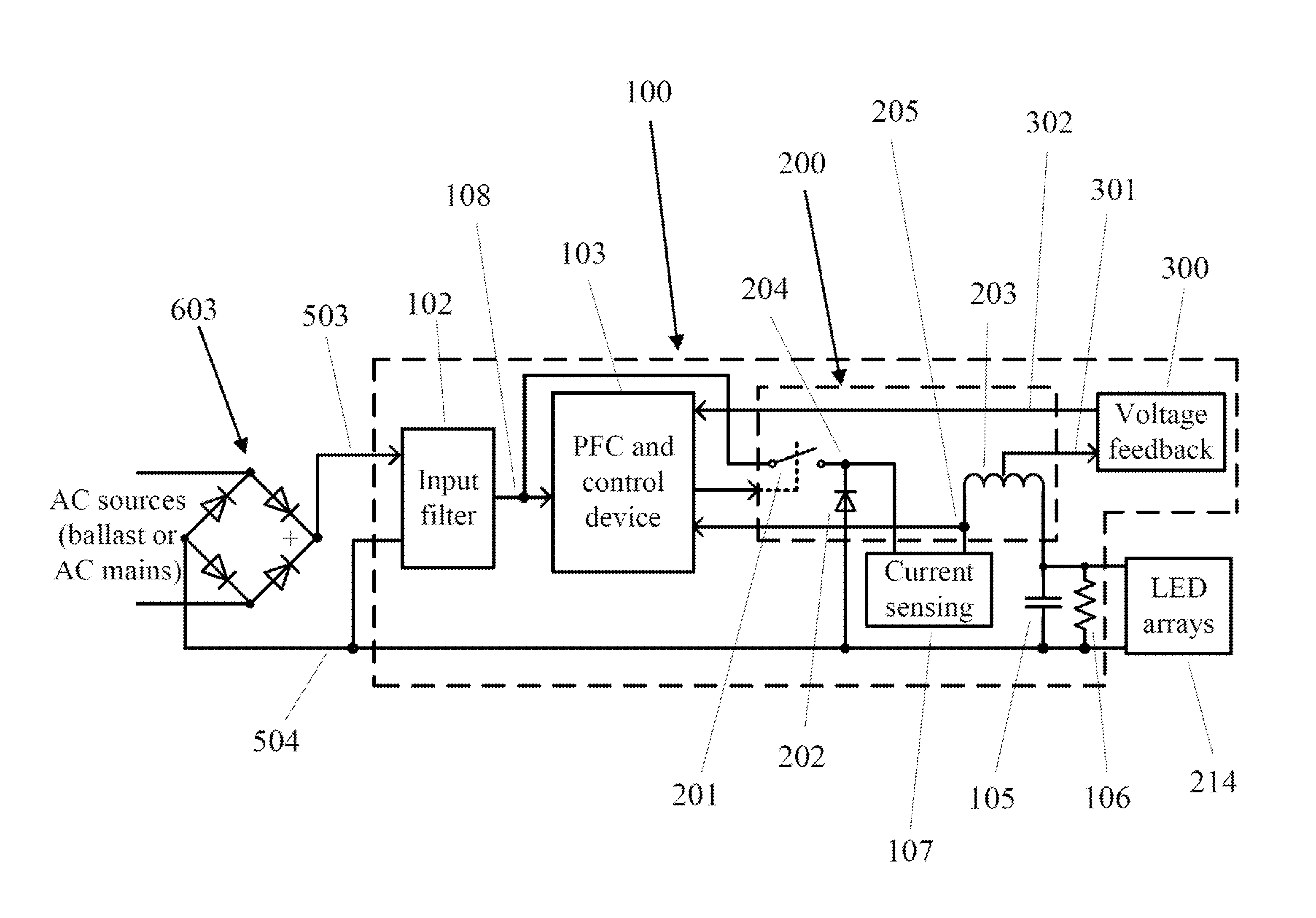
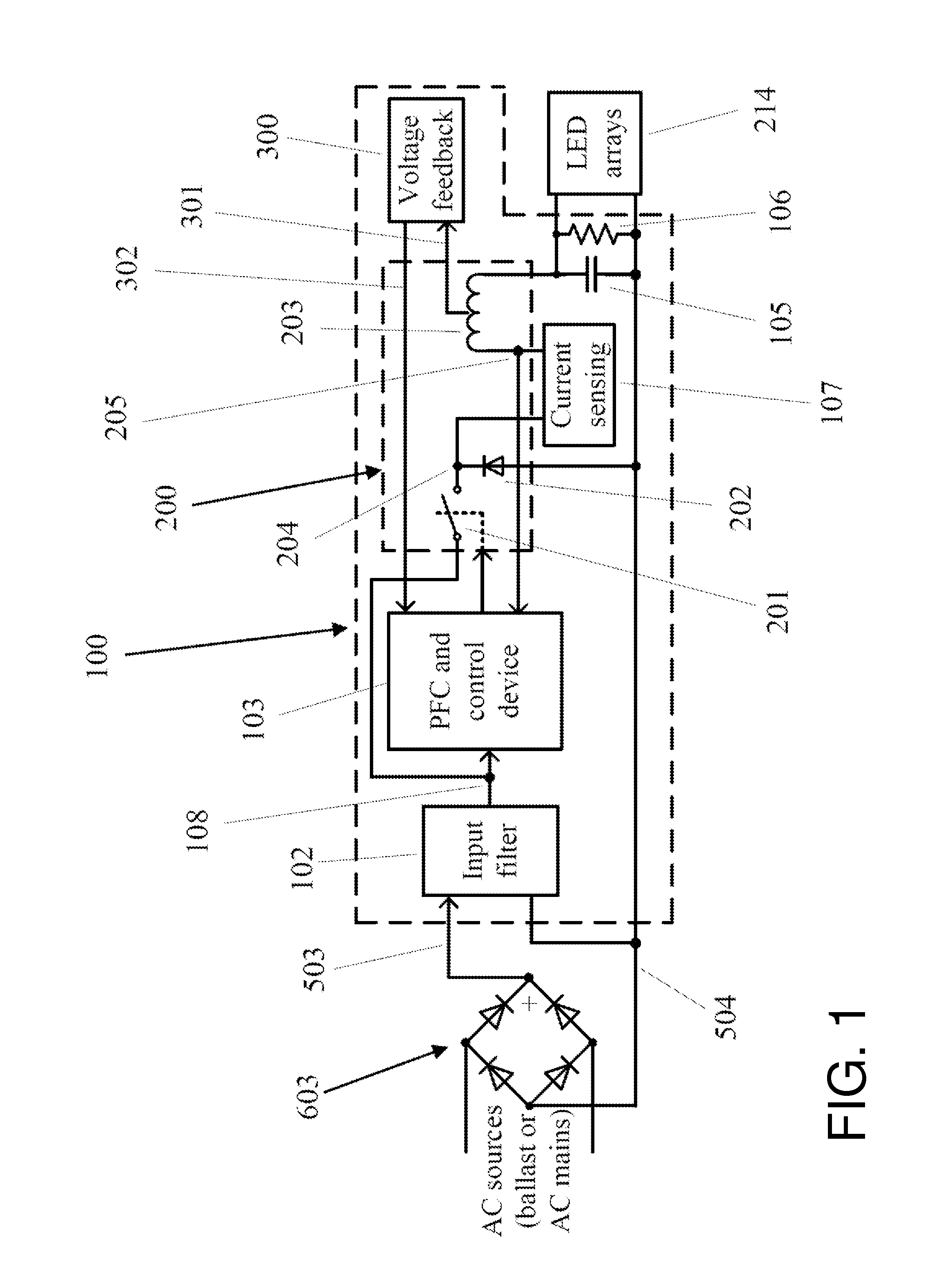
[0023]FIG. 1 is a block diagram of an all-in-one LED driving circuit used in a universal LLT lamp operable with either the AC mains or an electronic ballast according to the present disclosure. A bridge rectifier 603 connecting to an AC source, either the AC mains or an electronic ballast, converts alternating current (AC) into direct current (DC). The all-in-one driving circuit 100 connecting to the bridge rectifier 603 comprises an input filter 102 used to filter the input voltage and to suppress EMI noise created in the all-in-one driving circuit 100, a power factor correction (PFC) and control device 103, a Buck converter 200 in communicating with the PFC and control device 103, an output capacitor 105 in parallel with a resistor 106 connected to the Buck converter 200 to build up an output voltage and to power the LED arrays 214, a current sensing resistor 107, and a voltage feedback module 300 extracting partial energy from the output voltage to sustain the PFC and control dev...


PUM


Abstract

A linear light-emitting diode (LED)-based solid-state universal lamp using an all-in-one LED driving circuit with a power factor correction (PFC) and control device operates normally for a regulated power and current from either electronic ballast or AC mains. The all-in-one LED driving circuit is configured to operate in a wide range of input voltages and frequencies, especially for various high voltages and high frequencies associated with various electronic ballasts. With a cycle-by-cycle current control and power switching at a constant on-time and varied off-time, an over-rated surge current is limited, preventing occasional fire hazards occurred in the ballast. When two shock protection switches are used in two lamp bases in the lamp, the universal lamp fully protects a person from possible electric shock during initial installation and re-lamping.

Description

CROSS-REFERENCE TO RELATED APPLICATIONS[0001]This application is a continuation-in-part (CIP) application of U.S. patent application Ser. No. 14 / 465,174, filed Aug. 21, 2014 and currently pending, which is a CIP application of U.S. patent application Ser. No. 14 / 135,116, filed Dec. 19, 2013 and currently pending, which is a CIP application of U.S. patent application Ser. No. 13 / 525,249, filed Jun. 15, 2012 and issued as U.S. Pat. No. 8,749,167 on Jun. 10, 2014. The above-identified applications are incorporated herein by reference in its entirety.BACKGROUND[0002]1. Technical Field[0003]The present disclosure relates to linear light-emitting diode (LED) lamps that work with linear tube lamp fixtures configured to electrically connect either electronic ballast or the AC mains, and more particularly to a universal, shock and fire hazard-free linear LED tube lamp with a shock-protection mechanism.[0004]2. Description of the Related Art[0005]Solid-state lighting from semiconductor light-...

Claims


Application Information

Patent Timeline
Patent Type & Authority Patents(United States)
IPC IPC(8): H05B33/08F21K99/00F21V25/04H02M3/00H02M1/32H02M1/00H05B44/00
CPCH05B33/0884F21K9/175F21V25/04H02M1/32H02M3/00H05B33/0803H05B33/0806H05B33/0815H05B33/0845F21Y2101/02H02M2001/0058Y02B20/341Y02B20/347F21Y2115/10F21K9/278H05B45/355H05B45/3578Y02B20/30Y02B70/10H05B45/36H05B45/395H05B45/375H05B47/26H02M1/0058F21K9/27
Inventor HSIA, CHUNGHOSHEN, PAI-SHENG
Owner ALEDDRA INC
Why Eureka
Try Eureka