Device and method for wet floor cleaning

a technology for cleaning devices and floors, applied in the direction of carpet cleaners, cleaning using liquids, vehicle cleaning, etc., can solve the problem of bombarding with tiny droplets

Active Publication Date: 2016-03-22
VERSUNI HLDG BV
View PDF10 Cites 18 Cited by
  • Summary
  • Abstract
  • Description
  • Claims
  • Application Information

AI Technical Summary

Benefits of technology

[0004]It is an object of the present invention to mitigate or overcome the problem of liquid trails and puddles particularly due to non-level use of a floor cleaning device. According to one aspect of the invention, this problem is solved in that the cover has a cover surface which is provided with a plurality of ridges, said ridges forming liquid channels between them for transporting liquid to outfalls provided at lower ends of the liquid channels.
[0005]The cover surface faces the rotational axis of the brush. Consequently, when the brush is moistened and rotated during use, it will be bombarded with tiny droplets. These droplets will aggregate into drops and run downward along the cover surface under the action of gravity, thereby snowballing with other droplets to form (tiny) liquid streams. The ridges provided on the cover surface may be considered as levees that channel these liquid streams between them but do not allow the streams to merge. By keeping the streams separate, excessive accumulation of liquid at a single point is prevented, even when the cover is not in its level orientation. Instead, the channels between the ridges guide the liquid in relatively small quantities towards a lowest point or outfall associated with each channel, from where the liquid may trickle down onto the floor. The separate liquid channels constituted by the ridges thus allow a fine discharge distribution (satisfactory spread) of liquid collected by the cover surface, averting the creation of noticeable trails of liquid behind the cleaning device.

Problems solved by technology

Consequently, when the brush is moistened and rotated during use, it will be bombarded with tiny droplets.
The ridges provided on the cover surface may be considered as levees that channel these liquid streams between them but do not allow the streams to merge.

Method used


Image

  • Device and method for wet floor cleaning
  • Device and method for wet floor cleaning
  • Device and method for wet floor cleaning

Examples


Embodiment Construction

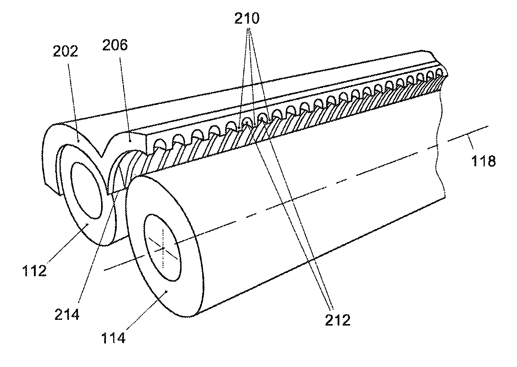
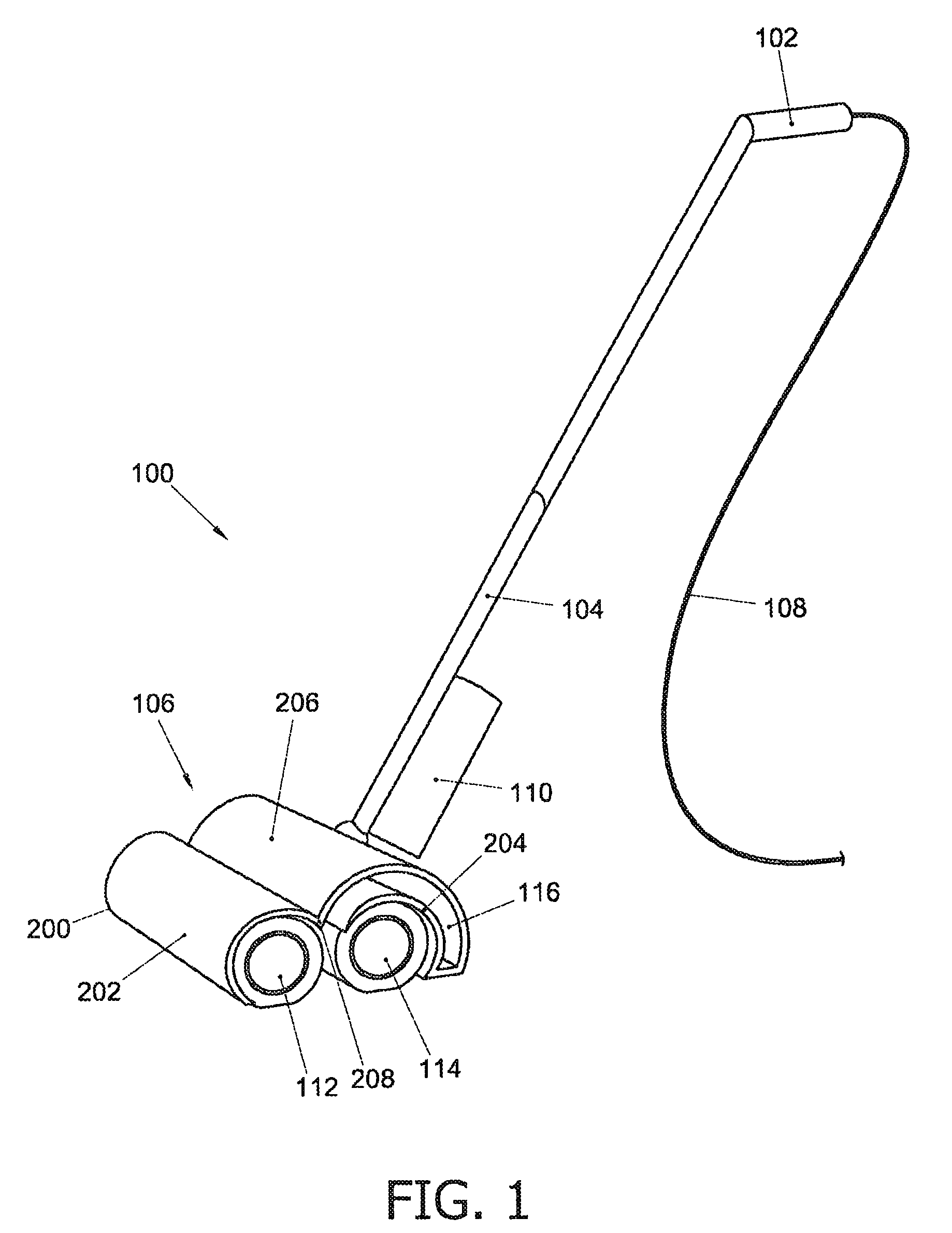
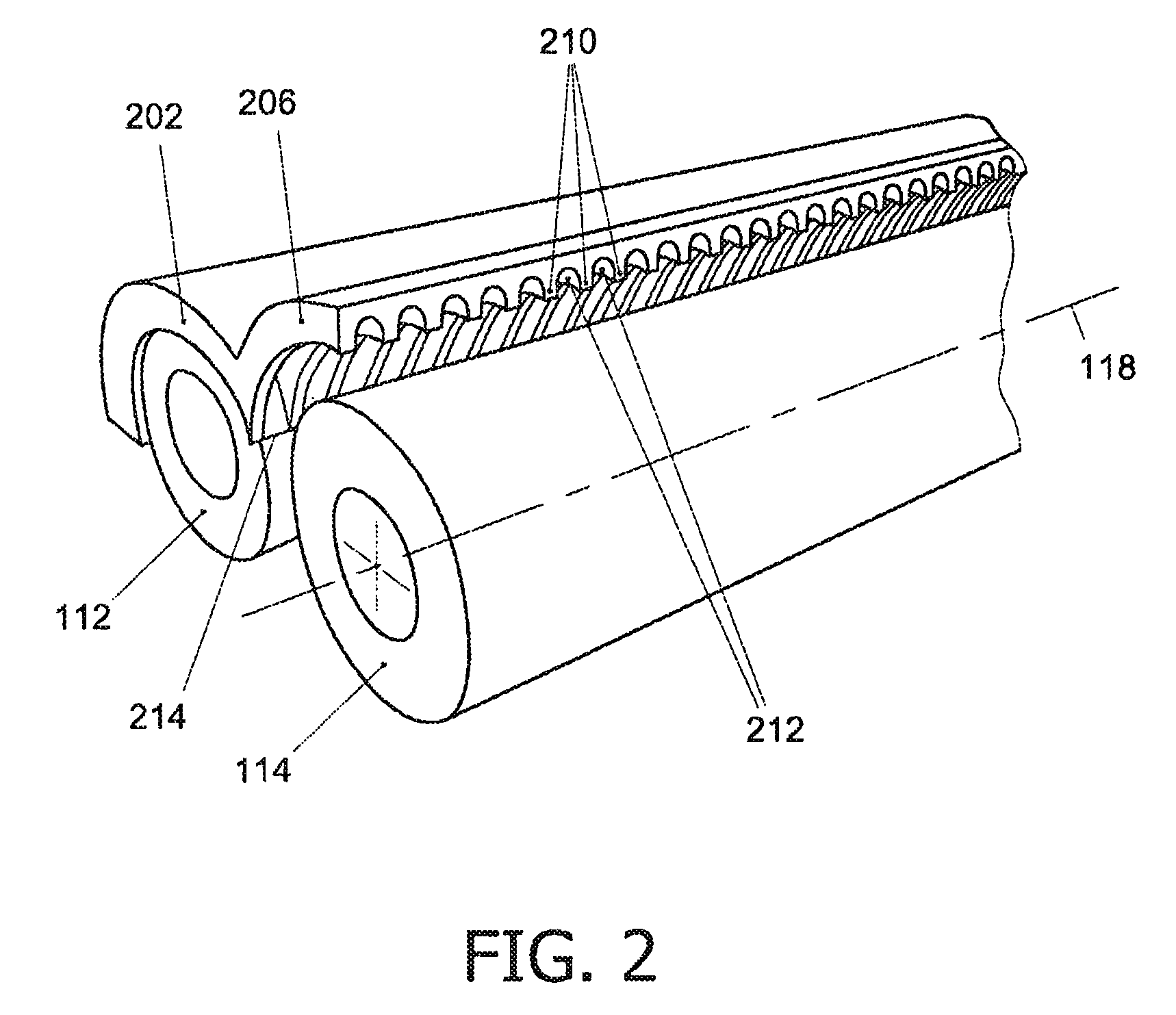
[0011]In the drawings, identical reference numerals denote the same or similar elements or acts. Shapes, sizes, angles and relative positions of elements in the drawings may not be drawn to scale and may be arbitrarily enlarged and positioned to improve drawing legibility. In addition, the examples of the floor cleaning device and its components are shown in a natural working orientation, i.e. a level or somewhat inclined orientation with respect to the horizontal. Consequently, where relevant, gravity points downward in the drawings.

[0012]FIG. 1 is a perspective view of an example of a wet floor cleaning device 100 according to the present invention. The device includes a handle 102 which is connected to a housing 106 via a connection rod 104. The housing 106 comprises a cover 200 and a waste or storage reservoir 116. The housing 106 further accommodates two brushes 112, 114 and an electromotor (not shown) for driving the brushes. A power cord 108 provided with a conventional plug ...


PUM


Abstract

A floor cleaning device is disclosed. It comprises a brush, which is rotatable around an axis of rotation, and a cover having a cover surface which faces the axis of rotation and has a plurality of ridges constituting liquid channels between them for transporting liquid to outfalls provided at lower ends of the liquid channels. In addition, a method of cleaning a floor is disclosed. The method comprises the steps of providing a brush, bringing the brush into contact with the floor, moistening the brush with a fluid, for example, a cleaning solution, rotating the brush, collecting droplets of fluid, released from the brush due to a centrifugal force associated with its rotational motion, in a plurality of liquid channels provided on a cover, and guiding the collected fluid through the liquid channels towards outfalls provided at lower ends of the liquid channels.

Description

FIELD OF THE INVENTION[0001]The present invention relates to equipment for floor maintenance, in particular to a wet floor cleaning device and to a method for cleaning a floor.BACKGROUND OF THE INVENTION[0002]Many wet floor cleaning apparatuses or devices comprise a rotatable brush which is continually wetted as it scrubs the surface of a floor to be cleaned. The brush is typically wetted with a cleaning solution that enhances the cleaning process. Unfortunately, the use of a wetted brush may leave behind cleaning solution residue in the form of a trail or a series of small puddles of cleaning solution. This even applies to cleaning devices that are capable of evenly and sparingly wetting the brush. A floor cleaning device comprising a brush that is rotatable around an axis of rotation, and a cover having a cover surface that faces the axis of rotation is known from U.S. Pat. No. 5,086,539. U.S. Pat. No. 5,086,539 discloses a carpet cleaning machine including a pair of spaced, long-...

Claims


Application Information

Patent Timeline
Patent Type & Authority Patents(United States)
IPC IPC(8): B08B3/04A47L11/33A47L11/40A47L11/08A47L11/292
CPCA47L11/292A47L11/085A47L11/33A47L11/4041A47L11/4077B08B3/04
Inventor MOES, FREDDY
Owner VERSUNI HLDG BV
Why Eureka
Try Eureka