Evacuated tube transport system

a technology of vacuum tube and vacuum tube, which is applied in the direction of positive displacement liquid engine, solar cell/heat pipe technology, and ways, etc., can solve the problems of significant energy input, air resistance becomes a significant factor, and none of the above problems have been successfully implemented for passenger travel

Active Publication Date: 2016-03-22
DALRYMPLE DAVID
View PDF19 Cites 28 Cited by
  • Summary
  • Abstract
  • Description
  • Claims
  • Application Information

AI Technical Summary

Benefits of technology

[0009]a first coupling mechanism and a first sealing mechanism arranged respectively to couple the capsule to another capsule at the end of the body while the capsules are moving and to establish a seal around the door and a corresponding door in the other capsule to enable passengers to move from one capsule to another through the doors without exposing the passengers to the pressure of the evacuated tube.
[0040]forming a connection between a rearwards most door of the injected capsule and a forwards most door of the originating capsule with the coupling and sealing mechanisms of the respective doors whereby passengers may move through the coupled capsules such that passengers intending to disembark at a second intermediate position may move to a rearwards most capsule without being exposed to the pressure of the evacuated tube;

Problems solved by technology

Such trains require significant energy input in order to be driven and, at the speeds they currently achieve, air resistance becomes a significant factor.
While such systems have been proposed, to the applicant's knowledge, none have been implemented successfully for passenger travel.

Method used


Image

  • Evacuated tube transport system
  • Evacuated tube transport system
  • Evacuated tube transport system

Examples


Embodiment Construction

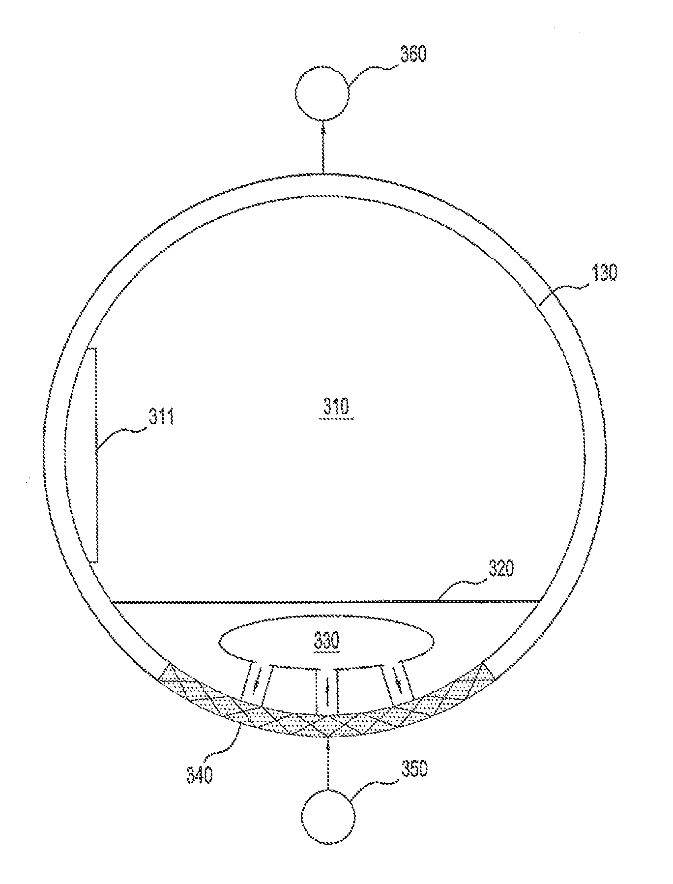
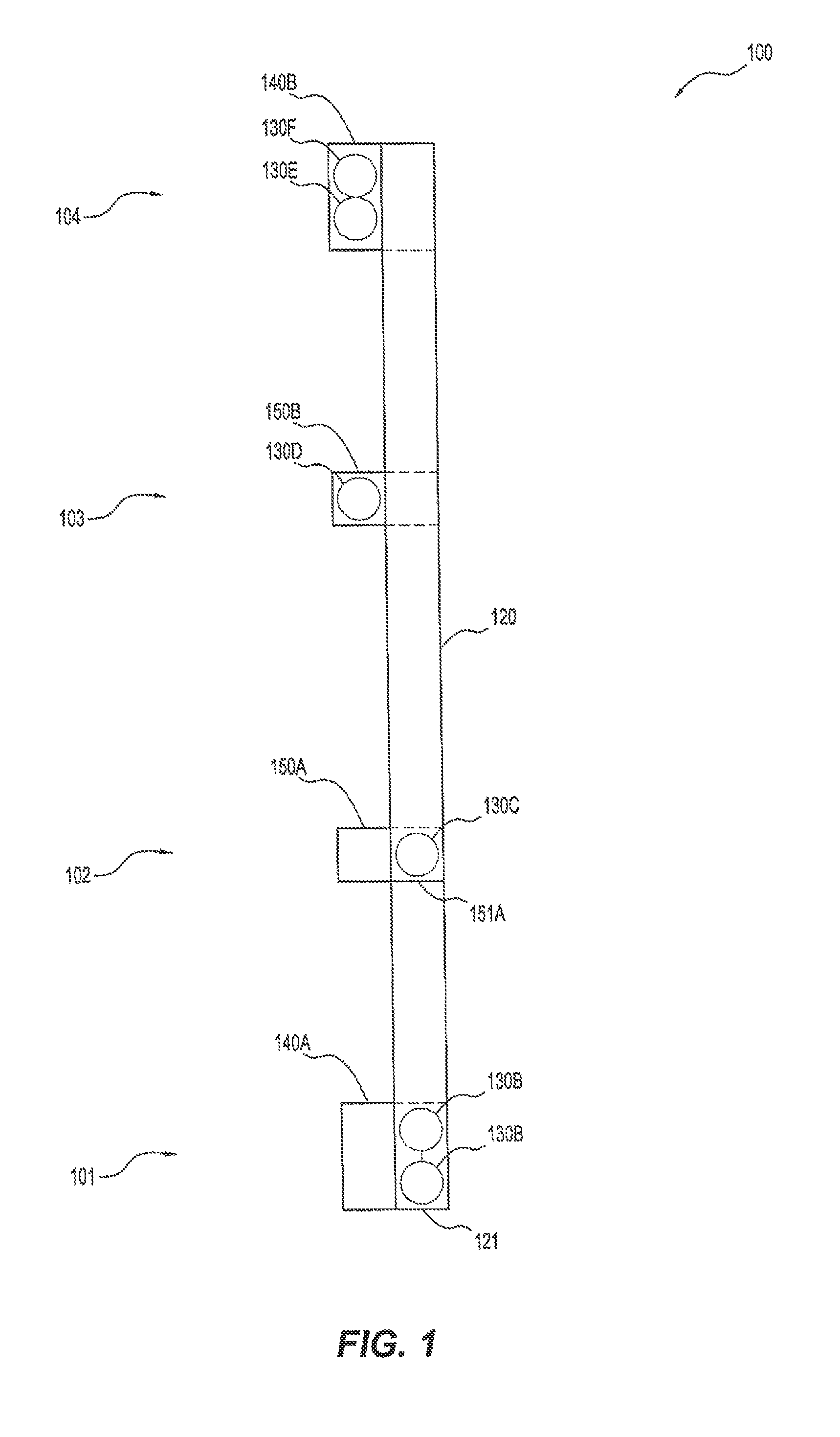
[0059]The drawings show an evacuated tube transport system 100 and a capsule 130 for the evacuated tube transport system 100. The evacuated transport system is capable of moving passengers and freight from an origin station 101 to a destination station 104. Embodiments of the invention allow capsules to be picked up and dropped off at intermediate stations 102, 103 while at least one capsule continues to move. As will be described in further detail below, the capsules 130 are moved within the evacuated tube 120 by the application of compressed air both at the origin and at spaced apart locations along the evacuated tube 120. The injected air is removed by spaced apart vacuum pumps in order to maintain the evacuated pressure of the tube. Compressed air is injected to the underside of the capsules both to apply motive force and to assist in the establishment of a cushion of compressed air underneath the capsule such that the system takes advantage of the so-called hovercraft effect.

[0...


PUM


Abstract

A capsule for an evacuated tube transport system, the capsule comprising a capsule body for carrying passengers within an evacuated tube; a first door disposed in a first end of the body; and a first coupling mechanism and a first sealing mechanism arranged respectively to couple the capsule to another capsule at the end of the body while the capsules are moving and to establish a seal around the door and a corresponding door in the other capsule to enable passengers to move from one capsule to another through the doors without exposing the passengers to the pressure of the evacuated tube.

Description

CROSS REFERENCE TO RELATED APPLICATIONS[0001]The present application is a continuation of International Application No. PCT / AU2011 / 001604, filed Dec. 13, 2011, which claims priority from Australian Application No. 2010905504, filed Dec. 16, 2010, and Australian Application No. 2011901931, filed May 18, 2011. The contents of the prior applications are incorporated herein by reference in their entirety.FIELD[0002]The present invention relates to an evacuated tube transport system as well as a transport method.BACKGROUND[0003]Trains are the dominant form of ground-based mass-transport. A wide variety of such trains are deployed ranging from diesel and electric powered trains to even more recent deployment of magnetic-levitation based trains. Such trains require significant energy input in order to be driven and, at the speeds they currently achieve, air resistance becomes a significant factor.[0004]One previously suggested alternative is to place a train or capsule in an evacuated tube...

Claims


Application Information

Patent Timeline
Patent Type & Authority Patents(United States)
IPC IPC(8): B61B13/08B61B13/10
CPCB61B13/10B61B13/08Y02T30/40B61B13/122Y02T30/00F04B25/005F04B39/10
Inventor DALRYMPLE, DAVID
Owner DALRYMPLE DAVID
Why Eureka
Try Eureka