Hydraulic lifting apparatus

Active Publication Date: 2016-03-22
HLBP DESIGN
View PDF53 Cites 8 Cited by
  • Summary
  • Abstract
  • Description
  • Claims
  • Application Information

AI Technical Summary

Benefits of technology

[0006]The invention described herein is intended to addresses the above needs. In particular, it is an objective of the invention to provide an apparatus that facilitates the efficient and convenient removal and replacemen

Problems solved by technology

Underground utility installations (such as sewer pipes, electrical cable conduits, and the like) have become increasingly complex.
This increasing complexity often requires frequent access by construction or maintenance personnel in order to install new utilities or upgrade and maintain existing utilities.
As a result, the manhole covers can be very heavy and difficult to lift, and may pose a safety risk to personnel who attempt t

Method used


Image

  • Hydraulic lifting apparatus
  • Hydraulic lifting apparatus
  • Hydraulic lifting apparatus

Examples


Example

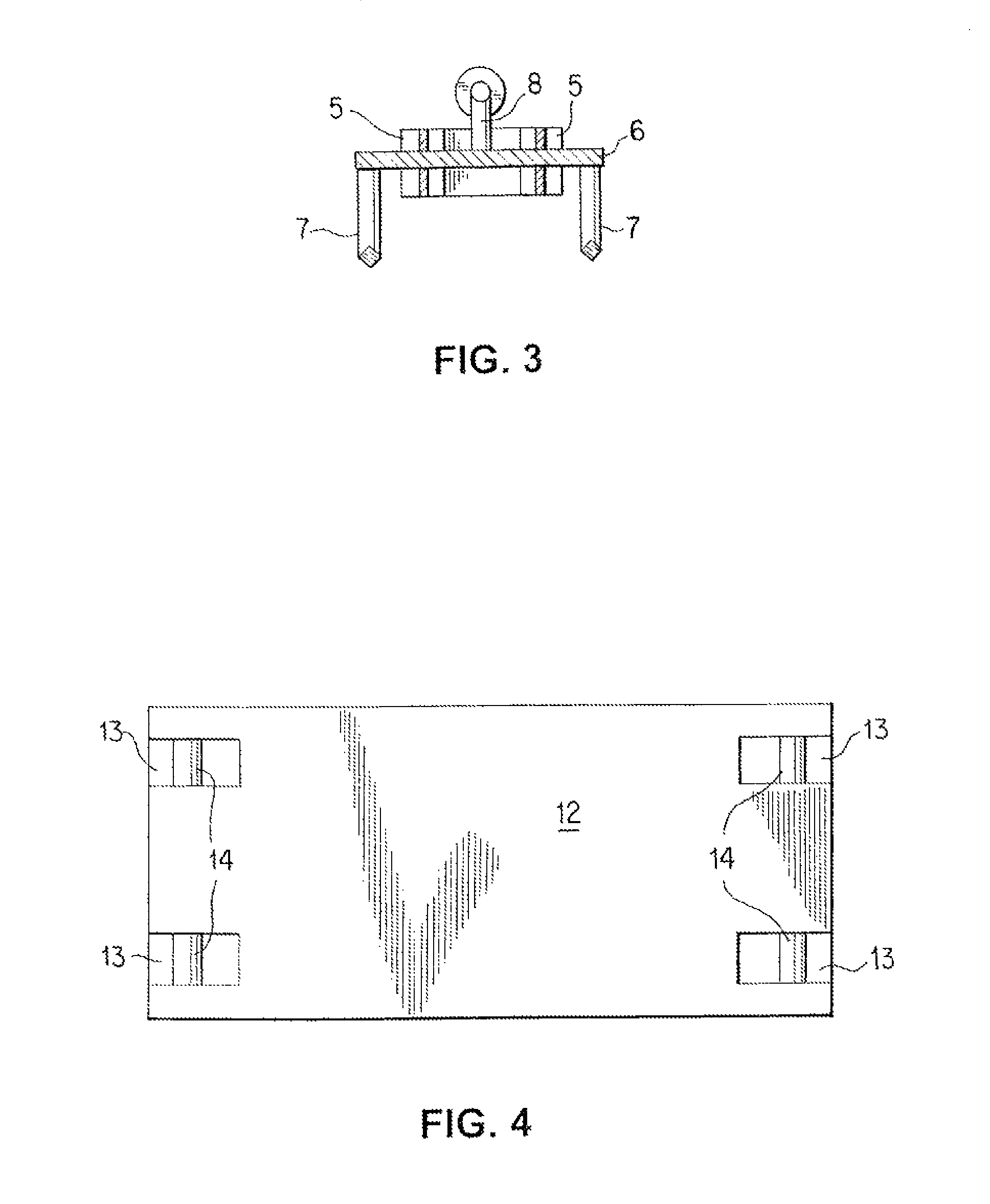
[0018]The principles of the present invention and their advantages are best understood by referring to the illustrated embodiment depicted in FIGS. 1-5 of the drawings, in which like numbers designate like parts.

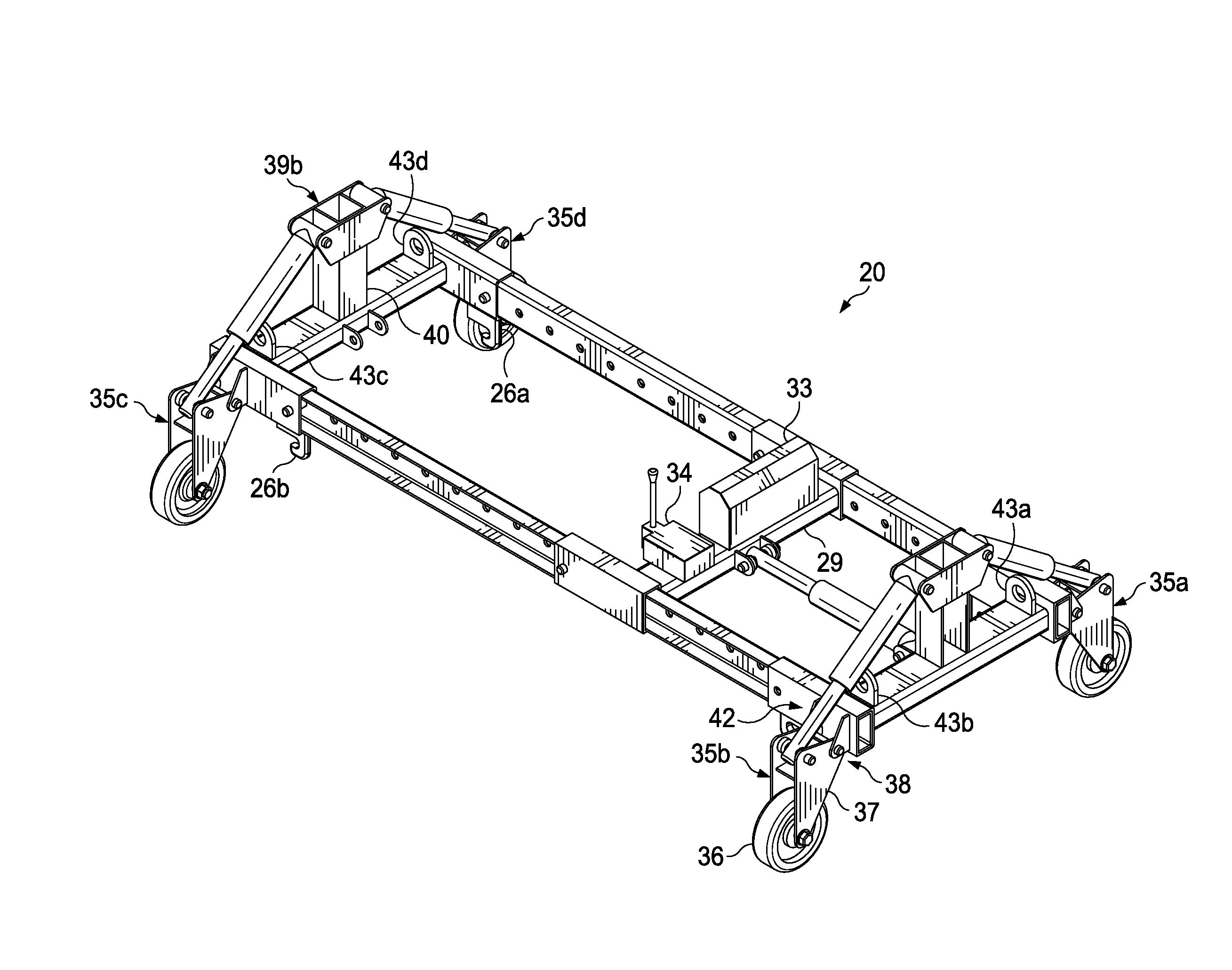
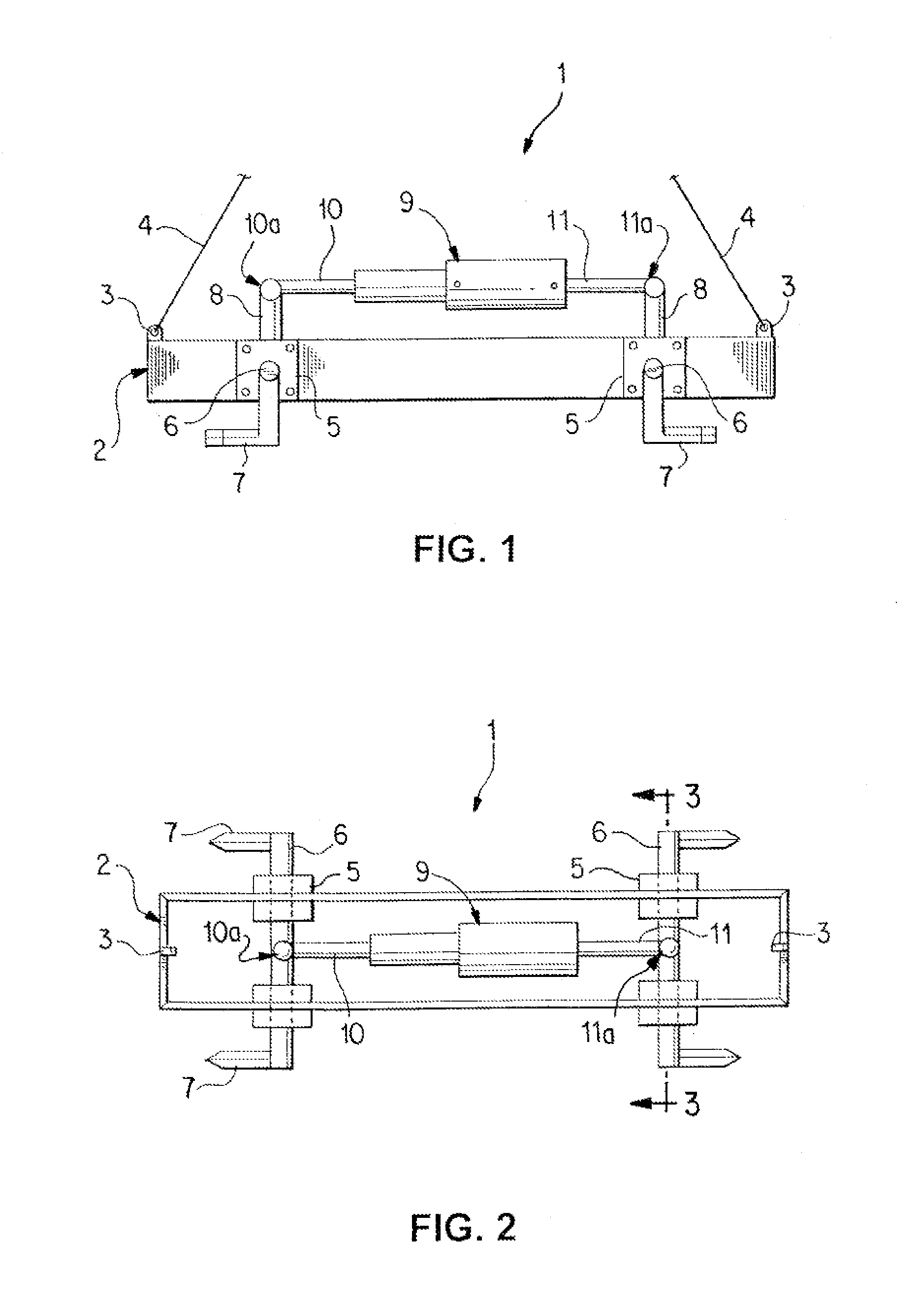
[0019]A hydraulic lifting apparatus 1 in accordance with one embodiment of the invention is shown in FIGS. 1 and 2. Hydraulic lifting apparatus 1 includes a lifting member 2. Lifting member 2 may be of any suitable construction. In the embodiment of the hydraulic lifting apparatus 1 shown in FIGS. 1 and 2, the lifting member 2 has an elongated box-type structure, constructed of four steel plates fastened together in a suitable fashion, for example, by welding. Alternatively, lifting member 2 could be constructed of a frame that includes tubular members. Lifting member 2 preferably includes a plurality of lifting points 3 to which an appropriate rigging structure may be affixed in order to lift the complete hydraulic lifting apparatus 1 with rigging or lifting equipment, such...


PUM

PropertyMeasurementUnit
Lengthaaaaaaaaaa
Angleaaaaaaaaaa
Distanceaaaaaaaaaa

Abstract

A lifting apparatus for lifting a rectangular manhole cover includes an elongated frame having first and second end assemblies each supporting a hook adapted to engage a corresponding lifting block on a rectangular manhole cover, at least one end assembly being movable with respects to the other end assembly to expand a distance between the hooks. An actuator moves movable end assembly to change the distance between the hooks and force the hooks into engagement with the lifting blocks on an adjacent rectangular manhole cover.

Description

CROSS-REFERENCE TO RELATED APPLICATION[0001]The present application is a continuation-in-part of copending U.S. patent application Ser. No. 12 / 880,824, filed Sep. 13, 2010.FIELD OF INVENTION[0002]The invention relates in general to a hydraulic lifting apparatus and, more particularly, to a hydraulic lifting apparatus used to lift rectangular manhole covers, street gratings, and the like.BACKGROUND OF INVENTION[0003]Underground utility installations (such as sewer pipes, electrical cable conduits, and the like) have become increasingly complex. This increasing complexity often requires frequent access by construction or maintenance personnel in order to install new utilities or upgrade and maintain existing utilities. Since these utility installations are located underground, access to them is generally accomplished through an entrance hole set at ground level. Personnel typically descend through the entrance hole into a vertical access conduit that permits access to the utility inst...

Claims


Application Information

Patent Timeline
IPC IPC(8): B66F19/00
CPCB66F19/005B66F19/00B66C1/28E02D29/1445Y10T29/49815E01C19/52
Inventor PANIO, MICHAEL T.BAYNON, JEFFREY
Owner HLBP DESIGN
Why Eureka
Try Eureka