Automatic irrigation system purging

a technology of automatic purging and irrigation system, which is applied in mechanical equipment, watering devices, transportation and packaging, etc., can solve the problems of large engine driven air compressor and reservoir, inability to control more than one zone, and inability to adjust the irrigation controller

Active Publication Date: 2016-03-29
PELLAERO
View PDF5 Cites 2 Cited by
  • Summary
  • Abstract
  • Description
  • Claims
  • Application Information

AI Technical Summary

Benefits of technology

[0013]An improved fully automated irrigation purge system according to the present invention utilizes a pressure purge method of discharging compressed air from a reservoir through selected irrigation zones with feedback from pressure switches to determine when to open and close each irrigation zone valve. No programming or user interaction is required beyond starting the system. The system can be used with any commercial irrigation controller. It can be successfully utilized in a wide variety of irrigation systems, with different number of zones, various pipe lengths, different pipe diameters, different number and variety of sprinkler heads or outlets, and varying degrees of slope of the terrain being irrigated. The air reservoir can be charged at any reasonable rate using a traditional 120 VAC air compressor. A higher airflow rate compressor will take less time to charge the reservoir than a lower airflow rate compressor, but both will accomplish the task. The air compressor and reservoir can be disconnected and used elsewhere when not needed for purging.
[0015]As a feature, the automatic purge system of the present invention can protect the irrigation system from high pressure conditions, be fully automatic, know when each zone has been sufficiently purged of water, handle multiple error conditions, maintain water valve settings during a power loss or unplugged condition, and seamlessly integrate with commercial irrigation controllers.
[0024]The invention may include a latching solenoid controlled by the purge controller for selectively allowing water to flow to the irrigation system. It may also include a quick-release connection for compressed air so that a homeowner may attach a portable air compressor. In some embodiments a control panel is provided and includes the switch and LEDs to notify the homeowner of the state of the system. Preferably, the purge controller uses the irrigation controller's power source (conventionally 24 VAC) to drive the irrigation zone valves. The purge controller's power source may be independent of the irrigation controller and they would be optically isolated from each other. This arrangement would protect the control circuitry of the irrigation controller.

Problems solved by technology

Irrigation systems installed in regions where cold climate conditions exist can be damaged by freezing of the water contained in the irrigation system and require winterization to prevent this damage.
The engine driven air compressor and reservoir are generally large, expensive, and noisy devices pulled by a truck or in the bed of a truck.
Also, irrigation controllers don't allow more than one zone to be on at a time.
This is time consuming and many times the remote valve boxes are covered by landscape material and difficult to locate.
It is well known that a home owner can achieve similar purge results with a smaller air compressor and reservoir but take significantly longer to run and may require multiple cycles per zone.
Both methods are labor intensive and require the operator to work outside in uncomfortable, cold climate conditions.
If they err on the conservative side and purge the system too soon, they may have landscape damage if warm, dry weather returns.
If they err on the aggressive side and purge the system too late, they may have irrigation system freeze damage.
Once purged, they are hesitant to turn the water back on due to the inability to have it purged again that same day and the expense involved.
It becomes cumbersome and time consuming to pull out the garden hose and water the landscaping during cold weather.
It utilizes an expensive, complicated air supply pump and feedback system where it maintains a consistent pressure in the zone by adjusting the speed of the air supply.
Variable speed motors require expensive controllers.
Also, in order to monitor the pressure in the system, a more expensive pressure sensor must be used to provide continuous pressure feedback.
Therefore, to reach a stable air pressure, large flow rates must be maintained and seem overkill for the simple task being accomplished.

Method used


Image

  • Automatic irrigation system purging
  • Automatic irrigation system purging
  • Automatic irrigation system purging

Examples


Embodiment Construction

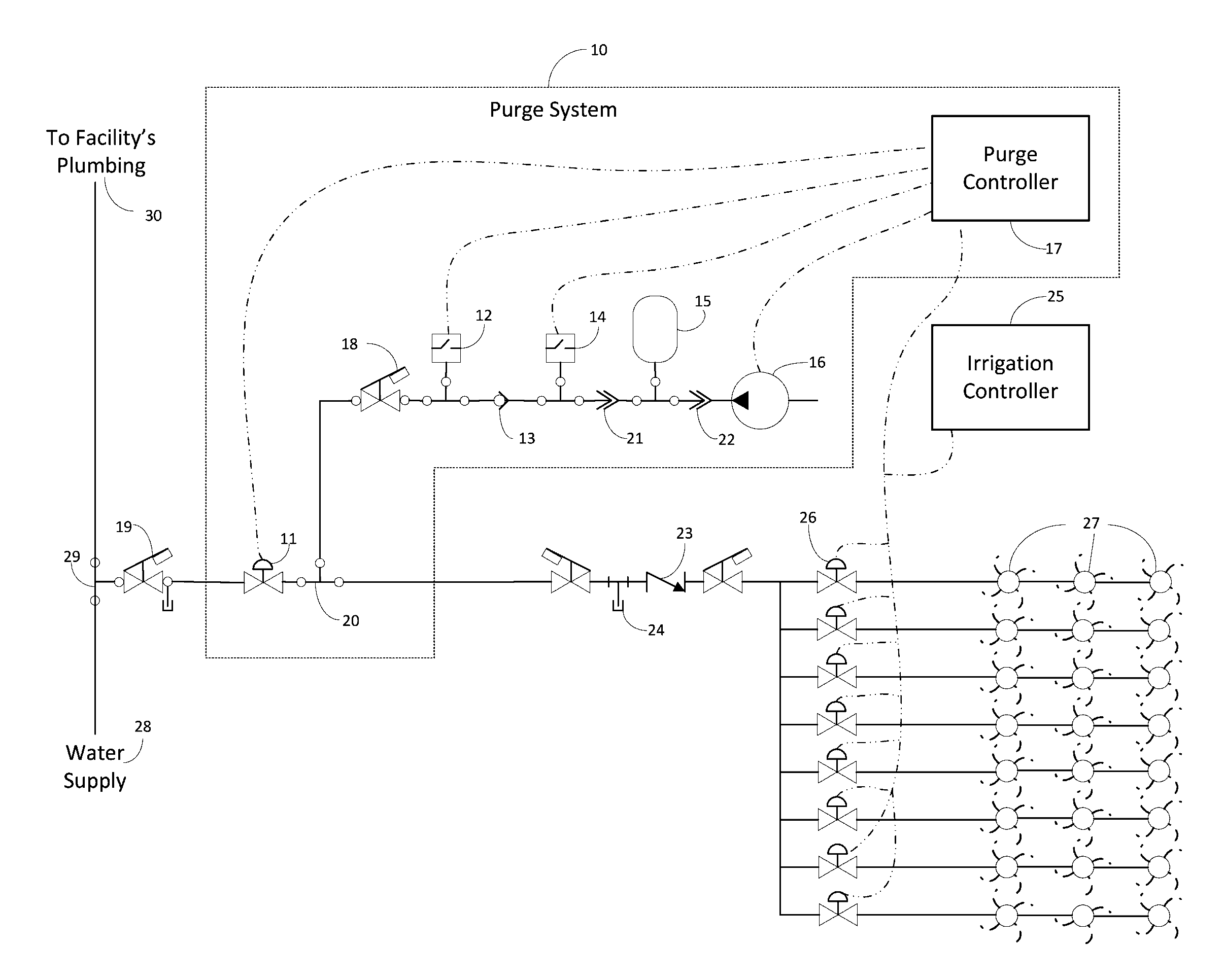
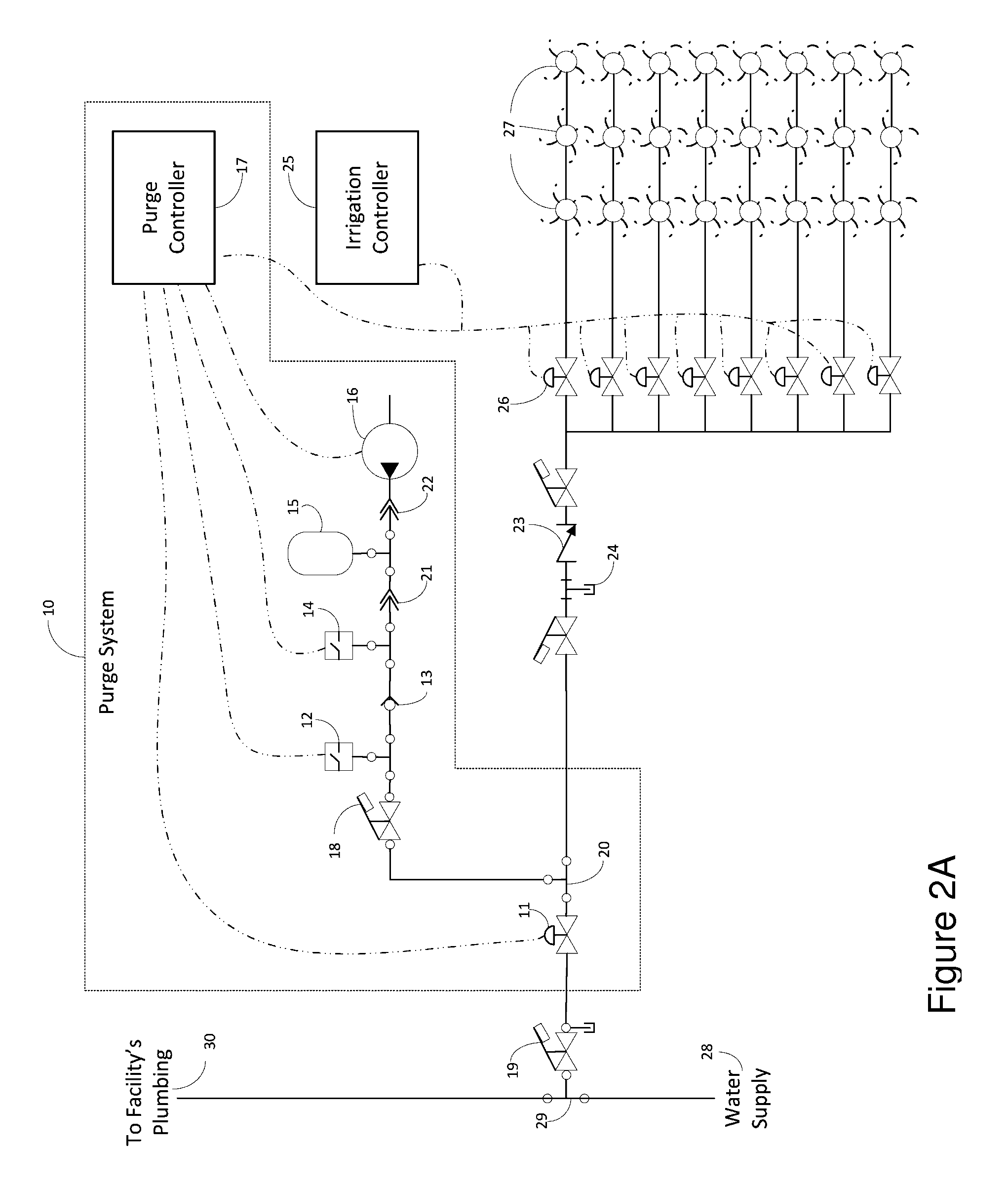
[0032]The following table lists elements of the illustrated embodiments of the invention and their associated reference numbers for convenience.

[0033]

TABLE 1REFERENCE NUMERALS10purge system11latching solenoid water valve12low-pressure switch13check valve14high-pressure switch15air reservoir16air compressor17Purge Controller18optional manual water valve19manual water valve with drain port20tee, inside structure air injection point21quick disconnect22quick disconnect23back flow check valve24outside structure air injection point25irrigation controller26irrigation zone valve(s)27sprinkler heads, drips, and misters28water supply29tee30to facility's plumbing31green LED32red LED33purge controller selector switch40zone valve control cables41air compressor indicator panel42pressure switches indicator panel43zone purging indicator panel44latching solenoid water valve indicator panel

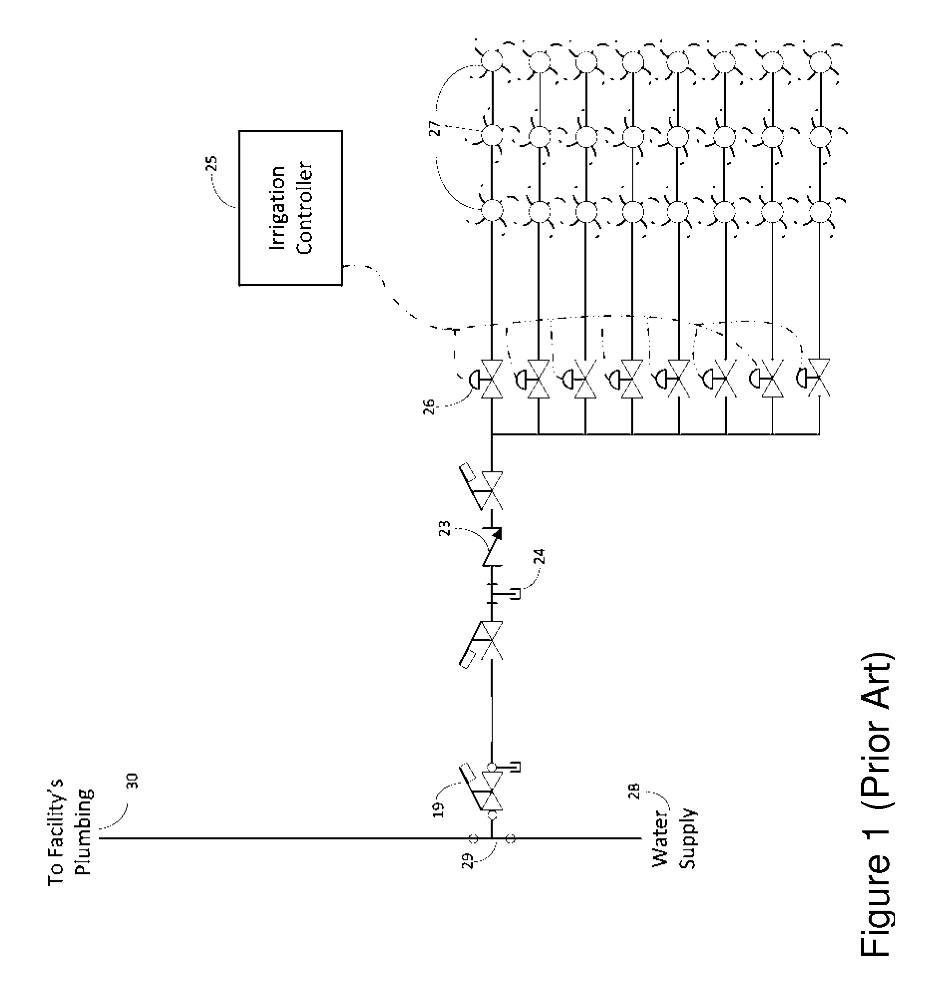
[0034]FIG. 1 (Prior Art) is a physical block diagram illustrating an existing irrigation system. Water supply 28...


PUM


Abstract

An automated irrigation purge system utilizes a pressure purge method of discharging compressed air from a reservoir through selected irrigation zones with feedback from pressure switches to determine when to open and close each zone valve. No programming or user interaction is required beyond starting the system. The system can operate with a wide variety of irrigation systems, with varying number of zones, pipe lengths, pipe diameters, number and variety of sprinkler heads or outlets, and terrain slope. The system tracks the pressure transition time from high pressure to low pressure for each zone as it is blown out. When the current transition time is within a specified range from the previous transition time, the system knows the water has been sufficiently purged from that zone. The purge system can protect the irrigation system from high-pressure conditions, handle multiple error conditions, and maintain water valve settings during power loss.

Description

BACKGROUND OF THE INVENTION[0001]1. Field of the Invention[0002]The present invention relates to methods and apparatus for automatically purging water from irrigation systems.[0003]2. Discussion of Related Art[0004]Irrigation systems installed in regions where cold climate conditions exist can be damaged by freezing of the water contained in the irrigation system and require winterization to prevent this damage. Compressed air is commonly used to force the water out of the irrigation system. Common practice is to hire a contractor who utilizes an industrial grade, engine driven, air compressor with a high flow rating at high pressures and a large volume capacity reservoir to connect to the existing irrigation system. The engine driven air compressor and reservoir are generally large, expensive, and noisy devices pulled by a truck or in the bed of a truck. The contractor must be granted access to the structure to manually turn off the main water supply. The air compressor and reservo...

Claims


Application Information

Patent Timeline
Patent Type & Authority Patents(United States)
IPC IPC(8): A01G25/16B05B15/02B05B12/04B05B12/02
CPCA01G25/16Y10T137/0419Y10T137/4238A01G25/165
Inventor DEAN, JR., ROBERT, E.HALL, TODD, R.
Owner PELLAERO
Why Eureka
Try Eureka